
- NOR Gate Definition: A NOR gate is defined as a logic gate that outputs high (1) only when all its inputs are low (0).
- Working Principle: The NOR gate works by combining an OR gate and a NOT gate, inverting the output of the OR gate.
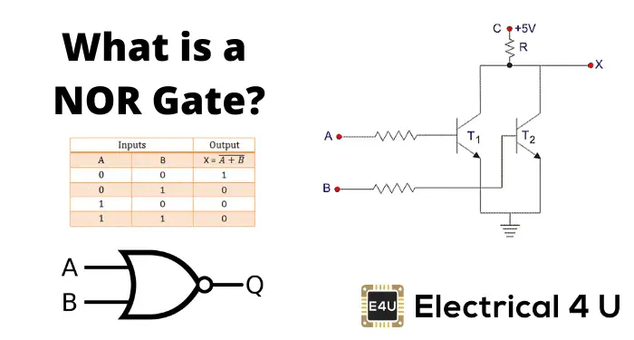
- Truth Table: The truth table of a NOR gate shows that the output is high only when all inputs are low.
- Universal Gate: The NOR gate is called a universal gate because it can be used to create all other basic logic gates.
- Transistor Circuit Diagram: A NOR gate’s circuit can be realized using two bipolar junction transistors in parallel.
What is a NOR Gate?
A NOR gate (“not OR gate”) is a logic gate that produces a high output (1) only if all its inputs are false, and low output (0) otherwise. Hence the NOR gate is the inverse of an OR gate, and its circuit is produced by connecting an OR gate to a NOT gate. Just like an OR gate, a NOR gate may have any number of input probes but only one output probe.
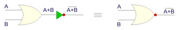
A NOT gate followed by an OR gate makes a NOR gate. The basic logic construction of the NOR gate is shown below:
The symbol of the NOR gate is similar to that of the OR gate, but with a bubble drawn at the output.
NOR Gate Truth Table
NOR gate means “not an OR gate” hence the output of this logic gate is just the reverse of that of an OR gate.
We know that the output of an OR gate is 0 only when all inputs of the OR gate are 0. Hence in the case of the NOR gate, the output is 1 only when all inputs are 0. In all other cases, that is for all other combinations of inputs the output is 0.
Truth tables list the output of a particular digital logic circuit for all the possible combinations of its inputs. The truth table of a 2 input NOR gate can be represented as:
You can see this is just the reverse of the 2 input OR gate truth table, which is as follows:
Like the OR gate, the NOR gate may also have more than two inputs.
A NOR gate is also referred to as a universal gate because it can be used to perform all binary operations.
There are three basic operations: AND, OR, and NOT. All complex binary operations can be realized using these three basic operations.
If we can prove that AND, OR, and NOT operations can be realized by using only the NOR gate, then we can easily say that all binary operations can be realized by using only NOR gates.
If you prefer a video explanation, you might find the video below on NOR gates useful.
In digital electronics, other logic gates include NOT gates, OR gates, NAND gates, XOR gates, XNOR gates.
Building a NOT Gate Using NOR Gates
If inputs of two inputs OR gate are 1, then the output is 1 and when both inputs of two inputs OR gate is 0, the output is 0.
As the NOR gate is reverse of the OR gate when both inputs of the NOR gate are 1, the output will be 0, and when both inputs of two inputs NOR gate 0, the output will be 1.
Now if we short circuit both inputs of a NOR gate, then we will get,
Where X is either 0 or 1.
So when X = 1, the output of the above gate is 1. This is nothing but a NOT operation. So we have seen a NOT gate can easily be realized by using the NOR gate only.
Building an OR Gate Using NOR Gates
NOR gate is an inverted OR gate, so the inverted NOR gate will be an OR gate. A NOT gate followed by a NOR gate will be equivalent to an OR gate. Here we will use the NOT gate which is realized from another NOR gate. The logic circuit of this OR gate will be as shown below,
Building an AND Gate from NOR Gate
The NOR operation of two input NOR gate is,

Now, according to D.Morgan’s theorem,
Now, if we put inverted A instead of A and inverted B instead of B in the above equation, we will get,
This is an AND operation.
So from the above equation, it is clear that if inputs of a NOR gate are inverted then the output will be AND equivalent.
So, if we connect the NOT gate at both inputs of a NOR gate, we will get an AND gate equivalent. As we are only allowed to use the NOR gate, we will use here the NOT gates which are realized from the NOR gate. The logical equivalent circuit will be as shown below,
Now we have proved that all three basic logical gates, NOT, OR, and AND gates can be realized by using only NOR gates. So any even much complex binary operation can be realized by using only a NOR gate hence it is quite justified to cal a NOR gate as a universal logic gate.
NOR Gate Circuit Diagram
NOR Gate Transistor Circuit Diagram
A NOR gate can be realized by using two bipolar junction transistors. The basic transistor circuit diagram is shown below. This circuit is made by two parallel-connected transistors.
In the circuit when both A and B are given +5 V, base of the both transistors gets quite a high potential to make the transistors ‘ON’. As both transistors T1 and T2 are in ON condition, supply voltage at terminal C gets the path to the ground through resistor R.
The entire supply voltage ideally drops across resistor R and the output terminal of the circuit will not get any voltage and hence it will be at logical 0 states.
Practically, a transistor cannot be ideally short-circuited in ON condition. There will be a voltage drop between emitter and collector of the transistor even in ON condition.
So practically the entire supply voltage will not drop across resistor R instead a small portion of it (0.6 V) is dropped across the transistor (saturated). That is, 5 – 0.6 = 4.4 V. Hence, the voltage appears at output terminal X is not practically zero instead it will be 0.6 V which is considered as logical 0.
Now, if either of inputs A and B are given with +5 V, the only corresponding transistor will be in ON condition. But in this case, also supply voltage will get the path to the ground through R and ON transistor and similarly, the output will be in logical 0 states which is 0.6 V.
Now if both of the inputs A and B are given with 0V or grounded, both transistors will be in OFF condition as in this case the base of both transistors does not have enough potential to make the transistors ON.
Since the supply voltage does not have a path to ground, it appears at the output X, resulting in a logical high (1) state.
Hence, in the circuit, the output is 1, only when both of the inputs are 0 and in all other conditions, the output is 0.
NOR Gate Integrated Circuits
There are many NOR gate Integrated Circuits (ICs) available in the market. A few of the most popular include:
IC 7402 contains four two inputs NOR gates.
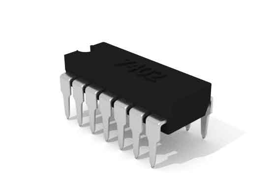
IC 7427 contains three inputs NOR gates.

IC 7425 contains two four inputs NOR gates.