

- Op Amp Definition: An operational amplifier (op amp) is a versatile component in electronic circuits, amplifying direct current from high input impedance to low output impedance.
- Op Amp Characteristics: Key characteristics of op amps include their ability to amplify signals with high gain and efficiency, pivotal for understanding their real-world deviations from ideal models.
- Pin Configuration: The IC 741 op amp is an example with an 8-pin setup including inverting and non-inverting inputs, output, power supply pins, and offset nulls.
- Applications of Op Amps: Op amps are fundamental in creating circuits like comparators, adders, and integrators, showcasing their flexibility in electronic design.
- AC Equivalent Circuit: The AC equivalent circuit of an op amp is essential for analyzing how internal resistance and voltage differences affect the output, offering a practical viewpoint for circuit design.
Operational amplifier or Op Amp as they are generally called are linear DC amplifiers. An op amp is a three-terminal device, one called the inverting terminal, one non-inverting terminal and the other is called the output terminal.
Below, you can see a pin diagram of a typical Op amp.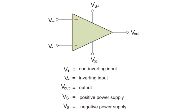
An ideal Op amp has the following characteristics:
- An infinite open-loop voltage gain.
- Infinite input impedance.
- Zero output impedance.
- Infinite common-mode rejection ratio.
- Infinite bandwidth.
- Zero offset voltage.
However, real op amps have characteristics a little deviated from what has been stated above. You can read more about the characteristics about op amps in other articles that we have written.
In this article, we are going to learn about the internal circuit of an op-amp IC. Along with that, we are also going to learn about the ac equivalent circuit of op-amp.
Pin Diagram of an Op Amp IC
The op-amp IC discussed in this article is the IC 741, which is an 8-pin integrated circuit. Below, we outline the pin configuration of IC 741.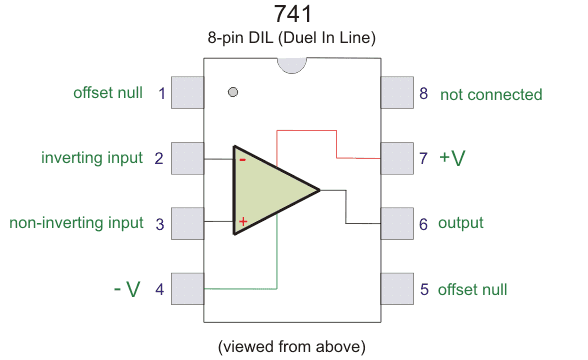
PIN 1 – Offset Null
PIN 2 – Inverting input
PIN 3 – non-inverting input
PIN 4 – negative voltage supply
PIN 5 – offset null
PIN 6 – output
PIN 7 – positive voltage supply
PIN 8 – not connected
The internal circuit diagram of an op-amp IC is given below: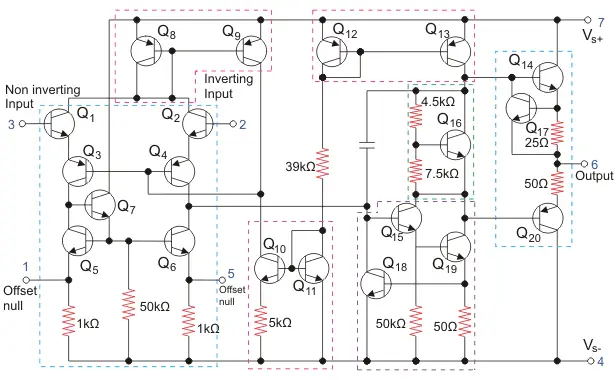
As you can see above, the non-inverting terminal and offset null are located at the left. The different terminals are marked in different colors. Op-amp is a collection of transistors and resistances as you can see from the picture.
Op-amp is used for different purposes. The 741 IC can be used as
- Adder
- Subtractor
- Comparator
- Voltage follower
- Integrator
- Differentiator
Here is a circuit diagram of Op-amp IC being used as a comparator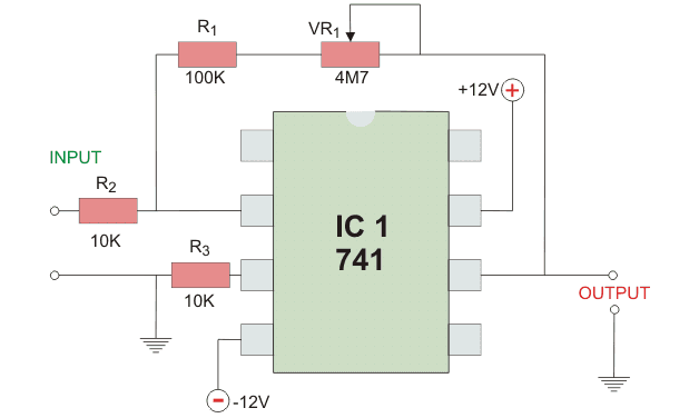
A comparator, as the name suggests, compares two items. Here, it compares two analog signals: one is a reference voltage and the other is the signal to be compared. The op-amp determines which signal has the greater magnitude.
AC equivalent Circuit of Op amp
The equivalent circuit of an op-amp is the circuit where the op-amp parameters are represented in terms of physical components. Such a representation is very helpful for analysis purposes.
Below, you can find the equivalent circuit of the op amp.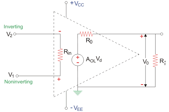
Circuit parameters like the internal resistance, output resistance, voltage gain are all represented by circuit components like Rin, Rout, etc.
V1 – non-inverting input voltage with respect to ground;
V2 – inverting input voltage with respect to ground;
Vee – negative supply voltage;
Vcc – positive supply voltage;
Vout – AOLVd = AOL(v1-v2);
Vd – the difference between inverting voltage and non-inverting voltage;
Ri – internal resistance of Op-amp;
R0 – output resistance of op-amp;
AOL – open-loop voltage gain.
The output voltage as you know is directly proportional to the difference between the input voltage.
The voltage AOLVd is the Thevenin’s equivalent voltage source whereas Ro is the Thevenin equivalent resistance as seen from the output terminal. This is the AC equivalent circuit of an Op amp. This is very useful for analyzing various op-amp circuits.