

- Thevenin Theorem Defined: Thevenin’s Theorem simplifies complex circuits into a single voltage source and a resistance in series with the load, ideal for easier analysis.
- Finding Thevenin Voltage: Essential for designing simplified circuits, finding the Thevenin voltage involves measuring the open-circuit voltage across the load terminals.
- Calculating Resistance: Thevenin resistance is found by deactivating all power sources in the original circuit and calculating the resistance from the load points.
- Theorem Limitations: While useful, Thevenin’s Theorem cannot be applied to circuits containing nonlinear elements or those with magnetic or controlled interactions.
- Comparison to Norton’s Theorem: Both theorems simplify complex circuits but use different components; Norton uses a current source and a parallel resistance.
What is Thevenin’s Theorem (Thevenin Equivalent)?
Thevenin theorem (also known as the Helmholtz–Thévenin theorem) states that any linear circuit containing only voltage sources, current sources, and resistances can be replaced by an equivalent combination of a voltage source (VTh) in series with a single resistance (RTh) connected across the load. This simplified circuit is known as the Thevenin Equivalent Circuit.
Thevenin’s theorem was invented by a French engineer Léon Charles Thévenin (hence the name).
Thevenin theorem is used to convert a complex electrical circuit to a simple two-terminal Thevenin equivalent circuit. A Thevenin equivalent circuit contains one Thevenin resistance and Thevenin voltage source connected with a load, as shown in the figure below.

Thevenin resistance (Rth) is also known as equivalent resistance. And Thevenin voltage (Vth) is an open-circuit voltage across load terminals.
This theorem is suited with only linear circuits. If the circuit has elements like semiconductor components or gas-discharging components, you can not apply Thevenin’s Theorem
Thevenin Equivalent Formula
The Thevenin equivalent circuit includes a voltage source and a resistance connected to a load, as illustrated in figure-1(b).
Thevenin equivalent circuit has a single loop. If we apply a KVL (Kirchhoff’s Voltage Law) to this loop, we can find the current passing through the load.
According to the KVL,
![\[ V_{th} = I ( R_{th} + R_L ) \]](https://www.electrical4u.com/wp-content/ql-cache/quicklatex.com-079f3d5f3f64b098df671df768059345_l3.png "Rendered by QuickLaTeX.com")
![\[ I = \frac{V_{th}}{( R_{th} + R_L)} \]](https://www.electrical4u.com/wp-content/ql-cache/quicklatex.com-f71cc16372390f917304b40506ab8e71_l3.png "Rendered by QuickLaTeX.com")
How to Find The Thevenin Equivalent Circuit
The Thevenin equivalent circuit contains Thevenin resistance and Thevenin voltage source. therefore, we have to find these two values for Thevenin equivalent circuit.
Thevenin Equivalent Resistance
To determine Thevenin resistance, first remove all power sources from the circuit. Short-circuit the voltage sources and open the current sources.
Hence, the remaining circuit has only resistances. Now, calculate the total resistance between the open connection points across load terminals.
The equivalent resistance is calculated by making series and parallel connection of resistances. And find a value of equivalent resistance. This resistance is also known as Thevenin resistance (Rth).
Thevenin Equivalent Voltage
To calculate Thevenin voltage, open-circuit the load and measure the voltage across the load terminals.
Thevenin equivalent voltage (Veq) is equal to the open-circuit voltage measured across two terminals of load. This value of the ideal voltage source is used in Thevenin equivalent circuit.
Thevenin Equivalent Dependent Source
When the circuit includes dependent sources, calculate Thevenin resistance differently, keeping these sources intact without opening or short-circuiting them.
There are two methods to find Thevenin resistance in the case of dependent sources.
Method 1
In this method, we have to find Thevenin voltage (Vth) and short-circuit current (Isc). Put these values in the below equation to find the Thevenin resistance.
![\[ R_{th} = \frac{V_{th}}{I_{sc}} \]](https://www.electrical4u.com/wp-content/ql-cache/quicklatex.com-dedf361c21339a671d70009e82f191ac_l3.png "Rendered by QuickLaTeX.com")

Thevenin voltage is same as the voltage across the terminals A and B. And we have the value of Thevenin voltage. Short-circuit current is obtained by shorting load terminals and find a current that passes through the shorted branch.

While calculating the short-circuit current, voltage and current sources remains as it is. Do not open or short circuit sources, whether it is depended or independent source.
Method 2
In this method, an extra known value of voltage source (V1) is connected across the load terminals. And find the current (I1) passing through the voltage source by keeping all dependent and independent sources.
After getting these values, put them in the below equation to find the Thevenin resistance.
![\[ R_{th} = \frac{V_1}{I_1} \]](https://www.electrical4u.com/wp-content/ql-cache/quicklatex.com-66819ae88a0b0800b44ed4f397934017_l3.png "Rendered by QuickLaTeX.com")

Thevenin Equivalent Circuit Examples
Example 1—Find the current passing the resistor R1

Step-1 Remove RL=4Ω branch.

Step-2 Find Thevenin equivalent voltage (Vth).
Apply KVL to the outer loop;
![\[ 12 = R_1 I_1 + R_2 I_2 \]](https://www.electrical4u.com/wp-content/ql-cache/quicklatex.com-d05f8d8e4841494c735f81356cae5375_l3.png "Rendered by QuickLaTeX.com")
(1) 
From the current source, we can find the second equation.
(2) ![\begin{equation*} I_2 - I_1 = 3 \] \end{equation*}](https://www.electrical4u.com/wp-content/ql-cache/quicklatex.com-da227b6bcd86aa83f9d66047a320aeda_l3.png "Rendered by QuickLaTeX.com")
By solving equation-1 and 2, we can find the value of current I1 and I2.
![\[ I_2 = 5A \]](https://www.electrical4u.com/wp-content/ql-cache/quicklatex.com-6fcc5a2dbb04fb24739d46c32c0faeba_l3.png "Rendered by QuickLaTeX.com")
The voltage across resistor R2=4Ω is the same as the voltage between A and B terminals. And it is the same as the Thevenin equivalent voltage.
Hence,
![\[ V_{AB} = V_{th} = I_2 \times R_2 \]](https://www.electrical4u.com/wp-content/ql-cache/quicklatex.com-a9a20fc7fe20ec0cc560604ba3f20c21_l3.png "Rendered by QuickLaTeX.com")
![\[ V_{th} = 5 \times 4 \]](https://www.electrical4u.com/wp-content/ql-cache/quicklatex.com-076070c87bc63d634c212d8260c35659_l3.png "Rendered by QuickLaTeX.com")
![\[ V_{th} = 20V \]](https://www.electrical4u.com/wp-content/ql-cache/quicklatex.com-02b851eea238321358783d5a1ba2ccdf_l3.png "Rendered by QuickLaTeX.com")
Step-3 Find Thevenin equivalent resistance (Rth).
To find the Thevenin equivalent resistance, we have to remove all voltage sources (as all sources are independent sources). To remove power sources; the voltage sources are open-circuited and current sources are short-circuited.
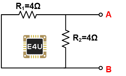
Here, both resisters are in parallel. Hence, the Thevenin equivalent resistance is;
![\[ R_{th} = 4 || 4 \]](https://www.electrical4u.com/wp-content/ql-cache/quicklatex.com-ef561a6dd76dd43d63cc5391ad03dd13_l3.png "Rendered by QuickLaTeX.com")
![\[ R_{th} = 2 \Omega \]](https://www.electrical4u.com/wp-content/ql-cache/quicklatex.com-b03c3e65031e9209e31809d71da29027_l3.png "Rendered by QuickLaTeX.com")
Step-4 Complete a Thevenin equivalent circuit using the values of Vth and Rth.
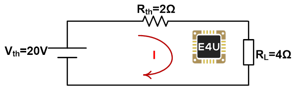
Apply KVL to the above circuit;
![\[ 20 = 2I + 4I \]](https://www.electrical4u.com/wp-content/ql-cache/quicklatex.com-d855c6f9c668075e69e4eb676ea42c46_l3.png "Rendered by QuickLaTeX.com")
![\[ 20 = 6I \]](https://www.electrical4u.com/wp-content/ql-cache/quicklatex.com-188eb2b4c0335ff9823dddfb8fe88414_l3.png "Rendered by QuickLaTeX.com")
![\[ I = \frac{20}{6} \]](https://www.electrical4u.com/wp-content/ql-cache/quicklatex.com-6b9fe11ff96a2b8783d50c6821eaa1d1_l3.png "Rendered by QuickLaTeX.com")
![\[ I = 3.333A \]](https://www.electrical4u.com/wp-content/ql-cache/quicklatex.com-ee5b1f78b8ac7f8296984a08cfb5d498_l3.png "Rendered by QuickLaTeX.com")
Hence, the current passing through the load is 3.333A.
Example 2— Find the current passing through the resistor R1

Step-1 Remove branch R1=4Ω.

Step-2 Calculate Thevenin equivalent voltage (Vth).
If you consider the outer loop, it will look like the below figure.

The current passing through the resistor R2=2Ω is 3A. hence, the voltage drops across the resistor R2 is;
![\[ V_B = V_{R2} = 2 \times 3 = 6 V \]](https://www.electrical4u.com/wp-content/ql-cache/quicklatex.com-fa8f2e5fff655fdb633d9087ef3904f1_l3.png "Rendered by QuickLaTeX.com")
We have open-circuited the branch having resistor R1. So, the current IA is equal to zero. And the voltage across the independent source is zero. therefore, we can neglect it while calculating Vth.
Terminal A is connected with a 16V voltage source.
![\[ V_A = 16V \]](https://www.electrical4u.com/wp-content/ql-cache/quicklatex.com-636eb9bb28d3ce3769169cbfcc191344_l3.png "Rendered by QuickLaTeX.com")
Terminal B is connected with a resistor R2. And the drop across the resistor is 6V.
So, potential difference between point A and B is;
![\[ V_{AB} = V_A - V_B \]](https://www.electrical4u.com/wp-content/ql-cache/quicklatex.com-96e1d55f73a7c1083e0e7b4b1c8cbd85_l3.png "Rendered by QuickLaTeX.com")
![\[ V_{AB} = 16 - 6 \]](https://www.electrical4u.com/wp-content/ql-cache/quicklatex.com-2a31b9605f92f5d5ac84a6c29d0038f7_l3.png "Rendered by QuickLaTeX.com")
![\[ V_{AB} = 10V \]](https://www.electrical4u.com/wp-content/ql-cache/quicklatex.com-db86562fa8bc5246230c514cac476a5e_l3.png "Rendered by QuickLaTeX.com")
This voltage is the same as the Thevenin equivalent voltage. Hence,
![\[ V_{th} = V_{AB} = 10V \]](https://www.electrical4u.com/wp-content/ql-cache/quicklatex.com-e66e91b978776f1dd68893adf6a81516_l3.png "Rendered by QuickLaTeX.com")
Step-3 Calculate the Thevenin equivalent resistance (Rth).
As the given circuit has a dependent source, we cannot directly find the value of Rth. For that, we will use above mentions methods. Here, we will use method-1.
In this method, we keep all dependent and independent sources as it is. And find the value of Thevenin equivalent voltage (Vth) and Short-circuit current (ISC).
We already have the value of Vth. Therefore, we need to calculate the value of ISC by shorting terminals A and B.

Apply KVL in the outer loop;
![\[ 16 - 4 I_A = 2 I_2 \]](https://www.electrical4u.com/wp-content/ql-cache/quicklatex.com-5ad0b20d16f5ae2cee4aae0b14a4c292_l3.png "Rendered by QuickLaTeX.com")
![\[ I_A = I_1 \]](https://www.electrical4u.com/wp-content/ql-cache/quicklatex.com-cda8d5ec8c6bde87ae3945bdf852c792_l3.png "Rendered by QuickLaTeX.com")
![\[ 16 - 4I_1 = 2I_2 \]](https://www.electrical4u.com/wp-content/ql-cache/quicklatex.com-ea69268cd92fd1610b624821c9f4de32_l3.png "Rendered by QuickLaTeX.com")
(3) 
We can find the second equation from the current source. And it is;
(4) 
By solving equation-3 and 4; we can find the value of current I1 and I2. And current I1 is the current that we need (ISC).
![\[ I_1 = I_{SC} =\frac{5}{3} A \]](https://www.electrical4u.com/wp-content/ql-cache/quicklatex.com-3f0e58112ec3b2eabe1eee38cf4368a2_l3.png "Rendered by QuickLaTeX.com")
Now, put these values in the below equation;
![\[ R_{th} = \frac{V_{th}}{ I_{SC}} \]](https://www.electrical4u.com/wp-content/ql-cache/quicklatex.com-bc0893cf2a5ef9df9671688f006cc4ea_l3.png "Rendered by QuickLaTeX.com")
![\[ R_{th} = 6 \Omega \]](https://www.electrical4u.com/wp-content/ql-cache/quicklatex.com-42d7821cc67aea85db74286e5db40490_l3.png "Rendered by QuickLaTeX.com")
Step-4 Thevenin equivalent circuit.
Now, put the values of Vth and Rth in the Thevenin equivalent circuit.
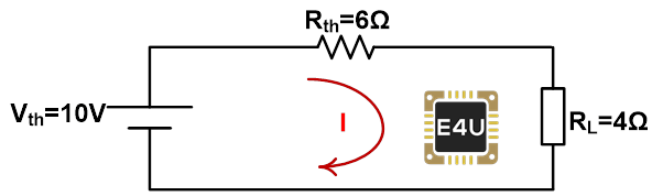
Apply KVL to the loop;
![\[ 10 = 6I + 4I \]](https://www.electrical4u.com/wp-content/ql-cache/quicklatex.com-27bff911050df036a2b5c8f5ebb92047_l3.png "Rendered by QuickLaTeX.com")
![\[ 10 = 10I \]](https://www.electrical4u.com/wp-content/ql-cache/quicklatex.com-96080a8e0053582790f64e2d26159573_l3.png "Rendered by QuickLaTeX.com")
![\[ I = 1A \]](https://www.electrical4u.com/wp-content/ql-cache/quicklatex.com-6927ba4f4a111cf2ac59beba4ec9040f_l3.png "Rendered by QuickLaTeX.com")
Thevenin and Norton Equivalent Circuits
Thevenin’s and Norton’s theorems are used in circuit analysis to convert a complex network into a simple network. In Thevenin’s theorem, a complex circuit converts into a Thevenin equivalent circuit. Similarly, in Norton’s theorem, a complex circuit converts into Norton’s equivalent circuit.
Norton’s equivalent circuit consists of a Norton equivalent resistance and Norton current source connected in parallel with the load. Norton’s equivalent circuit is as shown below figure.

The method to calculate, Norton equivalent resistance is the same as the Thevenin equivalent resistance.
![\[ R_{th} = R_N = R_{eq} \]](https://www.electrical4u.com/wp-content/ql-cache/quicklatex.com-5fac9d6bb5e12e26c478d73730abc6ec_l3.png "Rendered by QuickLaTeX.com")
Thevenin equivalent circuit consists of a single voltage source (Thevenin voltage) and Norton equivalent circuit consists of a current source (Norton current).
Consider a network converted into Thevenin and Norton equivalent circuit. In both circuits, if you find the current and voltage across the load, it will be the same values as the original circuit is same.
If we want to find the relation between Thevenin and Norton equivalent circuits, we need to find the relation between Thevenin voltage and Norton current.
This relation can be found by ohm’s law;
![\[ V_{th} = I_N R_{eq} \]](https://www.electrical4u.com/wp-content/ql-cache/quicklatex.com-341b48bba6c5ebfe7748aaadaeb7049a_l3.png "Rendered by QuickLaTeX.com")
Limitation of Thevenin Theorem
In circuit analysis, Thevenin’s theorem is used widely to solve complex circuits.
Still, there are some limitations in Thevenin’s theorem which are listed below.
- Thevenin’s theorem is not applicable to unilateral networks, where the performance depends on the current’s direction through the circuit components.
- Thevenin’s theorem applies only to networks that consist of linear elements. It cannot apply to nonlinear elements.
- There should not any magnetic coupling between the circuit and load.
- There should not any controlled sources, controlled from some other circuit part of the circuit.
Video Explanation of Thevenin’s Theorem
For those who would prefer a video explanation for finding the Thevenin equivalent circuit, we have provided one below.