

- Op-Amp Integrator Definition: An op-amp integrator is a circuit that uses an operational amplifier and a capacitor to calculate the integral of an input signal, outputting a voltage that reflects the cumulative effect of the input signal over time.
- Function: The primary function of an op-amp integrator is to convert waveforms, such as turning a square wave into a triangular wave, useful in signal processing and control systems.
- Design Principles: Effective integrator circuit design requires careful selection of resistance, capacitance, and op-amp characteristics, ensuring optimal performance across expected signal frequencies.
- Circuit Behavior: At its core, the integrator behaves like a low-pass filter, better processing low-frequency signals while reducing the impact of higher frequencies.
- Practical Applications: Integrators are essential in various technologies, including analog-to-digital conversion and waveform shaping, highlighting their versatility in electronics design.
What is an Op-Amp Integrator?
An op-amp integrator is a circuit that uses an operational amplifier (op-amp) and a capacitor to perform the mathematical operation of integration. Integration is the process of finding the area under a curve or function over time. An op-amp integrator produces an output voltage that is proportional to the negative integral of the input voltage, meaning that the output voltage changes according to the duration and amplitude of the input voltage.
An op-amp integrator can be used for various applications, such as analog-to-digital converters (ADCs), analog computers, and wave-shaping circuits. For example, an op-amp integrator can convert a square wave input into a triangular wave output, or a sine wave input into a cosine wave output.
How Does an Op-Amp Integrator Work?
An op-amp integrator is based on an inverting amplifier configuration, where the feedback resistor is replaced by a capacitor. The capacitor is a frequency-dependent element that has a reactance (Xc) that varies inversely with the frequency (f) of the input signal. The reactance of the capacitor is given by:
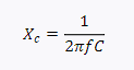
where C is the capacitance of the capacitor.
The schematic diagram of an op-amp integrator is shown below:
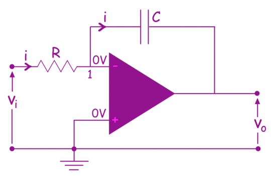
The input voltage (Vin) is applied to the inverting input terminal of the op-amp through a resistor (Rin). The non-inverting input terminal is connected to the ground, creating a virtual ground at the inverting input terminal as well. The output voltage (Vout) is taken from the output terminal of the op-amp, which is connected to the capacitor © in the feedback loop.
The working principle of an op-amp integrator can be explained by applying Kirchhoff’s current law (KCL) at node 1, which is the junction of Rin, C, and the inverting input terminal. Since no current flows into or out of the op-amp terminals, we can write:
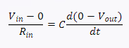
Simplifying and rearranging, we get:
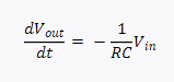
This equation shows that the output voltage is proportional to the negative derivative of the input voltage. To find the output voltage as a function of time, we need to integrate both sides of the equation:
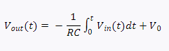
where V0 is the initial output voltage at t = 0.
This equation shows that the output voltage is proportional to the negative integral of the input voltage plus a constant. The constant V0 depends on the initial condition of the capacitor and can be adjusted by using an offset voltage source or a potentiometer in series with the capacitor.
What are some Characteristics and Limitations of an Op-Amp Integrator?
An ideal op-amp integrator has infinite gain and bandwidth, meaning that it can integrate any input signal with any frequency and amplitude without distortion or attenuation. However, in reality, there are some factors that limit the performance and accuracy of an op-amp integrator, such as:
- Op-amp characteristics: The op-amp itself has finite gain, bandwidth, input impedance, output impedance, offset voltage, bias current, noise, etc. These parameters affect the output voltage and introduce errors and deviations from the ideal behavior.
- Capacitor leakage: The capacitor in the feedback loop has some leakage resistance that allows a small current to flow through it, causing it to discharge over time. This reduces the integration effect and causes a drift in the output voltage.
- Input bias current: The op-amp has some input bias current that flows into or out of its terminals, depending on its type and design. This current creates a voltage drop across Rin and affects the input voltage seen by the op-amp. This also introduces an error in the output voltage.
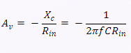
- Frequency response: The frequency response of an op-amp integrator depends on the reactance of the capacitor, which varies with frequency. As frequency increases, Xc decreases, making the capacitor act like an open circuit. As frequency decreases, Xc increases, making the capacitor act like a short circuit. Therefore, the frequency response of an op-amp integrator is inversely proportional to the frequency, or:
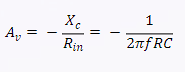
This equation shows that the voltage gain of an op-amp integrator decreases by 20 dB per decade (or 6 dB per octave) as the frequency increases. This means that an op-amp integrator acts like a low-pass filter that attenuates high-frequency signals and passes low-frequency signals.
However, this frequency response is not ideal for an integrator, as it introduces phase shifts and distortion in the output signal. Moreover, at very low frequencies, the voltage gain becomes very large and may exceed the op-amp’s output range, causing saturation or clipping. Therefore, some modifications are needed to improve the performance and accuracy of an op-amp integrator.
How to Improve an Op-Amp Integrator?
To optimize an op-amp integrator, consider modifications like adding a parallel resistor (Rf) with the capacitor. This adjustment curtails the voltage gain at lower frequencies, avoiding saturation, enhancing stability, and minimizing output voltage drift caused by capacitor leakage.
The voltage gain of this circuit is given by:
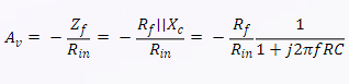
where Zf is the parallel impedance of Rf and Xc, and || denotes a parallel combination.
This equation shows that the voltage gain has a finite value at DC (f = 0), which is -Rf/Rin. As frequency increases, the voltage gain decreases by 20 dB per decade (or 6 dB per octave) until it reaches a corner frequency (fc), where Rf = Xc. At this frequency, the voltage gain is -Rf/2Rin. Beyond this frequency, the voltage gain decreases by 40 dB per decade (or 12 dB per octave) until it reaches the op-amp’s bandwidth limit.
The corner frequency can be calculated by equating Rf and Xc:

The corner frequency determines the range of frequencies over which the circuit behaves like an integrator. Ideally, this range should be as wide as possible for accurate integration. Therefore, Rf should be chosen to be as large as possible without causing saturation or instability.
- Adding a resistor in series with the capacitor: This resistor (Rs) limits the current through the capacitor and reduces the effect of input bias current on the output voltage. It also improves the high-frequency response of the circuit by creating a zero in the transfer function. The modified circuit is shown below:
The voltage gain of this circuit is given by:
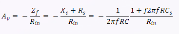
where Zf is the series impedance of Rs and Xc.
This equation shows that the voltage gain has a zero at DC (f = 0), where it is zero. As frequency increases, the voltage gain increases by 20 dB per decade (or 6 dB per octave) until it reaches a zero frequency (fz), where Rs = Xc. At this frequency, the voltage gain is -Rs/Rin. Beyond this frequency, the voltage gain decreases by 20 dB per decade (or 6 dB per octave) until it reaches a pole frequency (fp), where Rs + Xc = Rin. At this frequency, the voltage gain is -1. Beyond this frequency, the voltage gain decreases by 40 dB per decade (or 12 dB per octave) until it reaches decreases, making the capacitor act like an open circuit. As a result, the gain of the op-amp integrator decreases as frequency increases, following the relation:
This equation shows that the op-amp integrator has a frequency response that rolls off at -20 dB per decade, meaning that the output voltage decreases by a factor of 10 for every 10-fold increase in frequency. The frequency range where the op-amp integrator works effectively depends on the values of R and C, as well as the characteristics of the op-amp itself.
How to Design an Op-Amp Integrator?
The design of an op-amp integrator involves choosing appropriate values for R and C, as well as selecting a suitable op-amp for the desired application. Some factors to consider are:
- Integration time constant: The integration time constant (τ) is the product of R and C, and it determines how fast the capacitor charges or discharges in response to the input voltage. A larger τ means a slower integration, and a smaller τ means a faster integration. The value of τ should be chosen according to the expected frequency and duration of the input signal, as well as the required accuracy and stability of the output voltage. A general rule of thumb is to choose τ such that it is much larger than the period of the input signal, but much smaller than the duration of interest for integration.
- Output voltage range: The output voltage range of an op-amp integrator depends on the input voltage range, the integration time constant, and the supply voltage of the op-amp. The output voltage cannot exceed the supply voltage limits of the op-amp, otherwise, saturation will occur, and distortion will result. To avoid saturation, the output voltage range should be kept within a fraction of the supply voltage range, leaving some margin for error and noise. The output voltage range can be estimated by multiplying the input voltage range by τ and dividing it by a safety factor (such as 10).
- Op-amp characteristics: The op-amp used for an integrator should have a high open-loop gain, a high input impedance, a low output impedance, a low offset voltage, a low bias current, a low noise, and a wide bandwidth. These characteristics ensure that the op-amp can amplify and integrate any input signal with minimal error and distortion. However, these characteristics also depend on the frequency and temperature of operation, so they should be checked against the datasheet specifications of the op-amp. A newer op-amp is usually better than an older one in terms of performance and reliability.
What are some Examples of Op-Amp Integrators?
Here are some examples of op-amp integrators with different values of R and C, using a Texas Instruments TLV9002 op-amp with a supply voltage of ±5 V.
Example 1: R = 10 kΩ, C = 0.1 μF
This op-amp integrator has an integration time constant of τ = RC = 10 kΩ × 0.1 μF = 1 ms. This means that it can integrate input signals with frequencies up to about 100 Hz effectively. The output voltage range is estimated by multiplying the input voltage range (±5 V) by τ and dividing by 10, giving ±0.5 V. The frequency response rolls off at -20 dB per decade from about 100 Hz to about 250 kilohertz (kHz). This is the useful frequency range of integrator operation, and it is related to the op-amp gain-bandwidth product (GBW). The GBW is a constant value that indicates the maximum frequency at which the op-amp can provide a certain gain. For example, if the GBW of an op-amp is 1 MHz, it means that the op-amp can provide a gain of 1 at 1 MHz, a gain of 10 at 100 kHz, a gain of 100 at 10 kHz, and so on. The GBW can be found in the datasheet of the op-amp and is usually specified for an open-loop configuration.
Example 2: R = 100 kΩ, C = 0.01 μF
This op-amp integrator has an integration time constant of τ = RC = 100 kΩ × 0.01 μF = 1 ms, which is the same as the previous example. However, the output voltage range is different, because the input voltage range is different. Assuming an input voltage range of ±0.5 V, the output voltage range is estimated by multiplying the input voltage range (±0.5 V) by τ and dividing by 10, giving ±0.05 V. The frequency response rolls off at -20 dB per decade from about 100 Hz to about 250 kHz, which is also the same as the previous example.
Example 3: R = 1 kΩ, C = 1 μF
This op-amp integrator has an integration time constant of τ = RC = 1 kΩ × 1 μF = 1 ms, which is again the same as the previous examples. However, the output voltage range is different, because the input voltage range is different. Assuming an input voltage range of ±50 V, the output voltage range is estimated by multiplying the input voltage range (±50 V) by τ and dividing by 10, giving ±5 V. The frequency response rolls off at -20 dB per decade from about 100 Hz to about 250 kHz, which is also the same as the previous examples.
Conclusion
An op-amp integrator is a circuit that uses an op-amp and a capacitor to perform the mathematical operation of integration. It produces an output voltage that is proportional to the negative integral of the input voltage over time. It can be used for various applications, such as analog-to-digital converters, analog computers, and wave-shaping circuits.
The design of an op-amp integrator involves choosing appropriate values for R and C, as well as selecting a suitable op-amp for the desired application. Some factors to consider are:
- Integration time constant: It determines how fast the capacitor charges or discharges in response to the input voltage. It should be chosen according to the expected frequency and duration of the input signal, as well as the required accuracy and stability of the output voltage.
- Output voltage range: It depends on the input voltage range, the integration time constant, and the supply voltage of the op-amp. It should be kept within a fraction of the supply voltage range, leaving some margin for error and noise.
- Op-amp characteristics: The op-amp should have a high open-loop gain, a high input impedance, a low output impedance, a low offset voltage, a low bias current, a low noise, and a wide bandwidth. These characteristics ensure that the op-amp can amplify and integrate any input signal with minimal error and distortion.
The frequency response of an op-amp integrator depends on the reactance of the capacitor, which varies inversely with frequency. As frequency increases, the gain of the op-amp integrator decreases, following the relation:
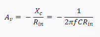
This equation shows that the op-amp integrator has a frequency response that rolls off at -20 dB per decade, meaning that the output voltage decreases by a factor of 10 for every 10-fold increase in frequency. The frequency range where the op-amp integrator works effectively depends on the values of R and C, as well as the characteristics of the op-amp itself. The GBW of the op-amp is a constant value that indicates the maximum frequency at which the op-amp can provide a certain gain.