- Digital Comparator Definition: A digital comparator is defined as a circuit that compares two binary numbers and indicates whether one is greater, equal, or smaller than the other.
- Single-Bit Digital Comparator: Compares two single-bit binary numbers and provides outputs for greater, equal, and smaller conditions.
- Multi-Bit Digital Comparator: Extends comparison to multi-bit binary numbers, often using a 4-bit comparator as a basic building block.
- Working Principle: The comparator evaluates each bit, starting from the most significant, to determine the output condition.
- IC 7485: A 4-bit digital comparator IC that can be cascaded for comparing larger binary numbers, with specific input and output terminals for seamless integration.
A digital comparator is defined as a circuit that compares the magnitudes of two binary numbers. One number can be greater, equal, or smaller than the other. To understand this better, consider two single-bit binary numbers, A and B. Each can either be 0 or 1. We can design a circuit with two inputs (A and B) and three outputs for the conditions A > B, A = B, and A < B. We label these outputs G, E, and L, respectively.
We want,
G = 1 (logically 1) when A > B.
B = 1 (logically 1) when A = B.
And
L = 1 (logically 1) when A < B.
If we successfully design this logic circuit, it will confidently compare two single bit binary numbers A, B and gives high state at respective output terminal according to the comparison conditions of A and B.
| A | B | G | E | L |
| 0 | 0 | 0 | 1 | 0 |
| 0 | 1 | 0 | 0 | 1 |
| 1 | 0 | 1 | 0 | 0 |
| 1 | 1 | 0 | 1 | 0 |
When, A = 0 and B = 0, then A = B and E = 1
When, A = 0 and B = 1, then A < B and L = 1
When, A = 1 and B = 0, then A > B and G = 1
When, A = 1 and B = 1, then A = B and E = 1
Now from above table, we get,
This circuit can be realized as,
As the above can only compare two single bit binary numbers, it is called single bit digital comparator.
The binary number system usually uses multi-bit numbers, typically 4 bits or more. Let’s design a 4-bit digital comparator to better understand how comparators work.
Suppose, there are two 4 bit binary numbers,
Let us compare those two numbers
Condition (1), when A1 > B1 i.e. A1 = 1 and B1 = 0, ⇒ A > B or G = 1.
Condition (2), when A1 = B1 and A2 > B2 i.e. A2 = 1 and B2 = 0 ⇒ A >B or G = 1.
Condition (3), when A1 = B1 and A2 = B2 and A3 > B3 i.e. A3 = 1 and B3 = 0 ⇒ A >B or G = 1.
Condition (4), when A1 = B1, A2 = B2, A3 = B3 and A4 > B4 i.e. A4 = 1 and B4 = 0 ⇒ A > B or G = 1.
Hence, G = 1 if either of the above equations is true,
Similarly,

Now,
Again when,
The logic circuit can be drawn from the above equations (i), (ii) and (iii).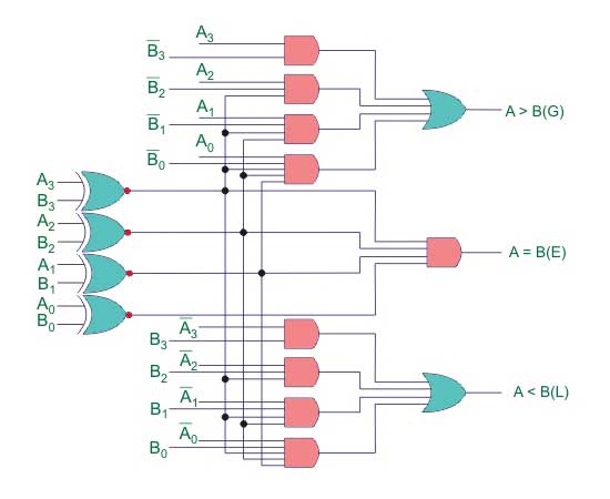
This is 4bit digital comparator.
IC of Digital Comparator
The Integrated Circuit (IC) available for 4 bit digital comparator is IC 7485. For more bit comparison, more than one such ICs can be cascaded. This IC has three terminals, labeled as (A < B)in, (A = B)in and (A > B)in and other three terminals labeled as, as (A < B)out, (A = B)out and (A > B)out. During cascading of two 7485 ICs, (A < B)out, (A = B)out and (A > B)out of lower order IC would be connected to (A < B)in, (A = B)in and (A > B)in of higher order IC, respectively.