- Winding Factor Definition: Winding factor is defined as the product of the pitch factor and distribution factor.
- Pitch Factor: The pitch factor is the ratio of the phasor sum of induced emfs to their arithmetic sum and is always less than unity.
- Full Pitched vs. Short Pitched Coils: In full-pitched coils, emfs sum arithmetically due to a 180° phase angle, while in short-pitched coils, they sum vectorially with a phase angle less than 180°.
- Distribution Factor: Distribution factor measures the resultant emf of distributed windings compared to concentrated windings, always being less than unity.
- Harmonics in Design: By choosing appropriate chording angles, designers can optimize windings to reduce unwanted harmonic effects.
Before learning about the winding factor, it’s important to understand pitch factor and distribution factor, as the winding factor is their product.
If we denote winding factor with Kw, pitch factor with Kp and distribution factor with Kd, we can write
The pitch factor and distribution factor are explained below one by one.
Pitch Factor
In a short-pitched coil, the induced emf from the two coil sides adds vectorially, creating the resultant emf. The phase angle between the induced emfs is less than 180°. In a full-pitched coil, this angle is exactly 180°.
Hence, the resultant emf of a full pitched coil is just the arithmetic sum of the emfs induced on both sides of the loop. We well know that vector sum or phasor sum of two quantities is always less than their arithmetic sum. The pitch factor is the measure of resultant emf of a short-pitched coil in comparison with resultant emf of a full pitched coil.
Hence, it must be the ratio of phasor sum of induced emfs per coil to the arithmetic sum of induced emfs per coil. Therefore, it must be less than unity.
Let us assume that, a coil is short pitched by an angle α (electrical degree). Emf induced per coil side is E. The arithmetic sum of induced emfs is 2E. That means, 2E, is the induced voltage across the coil terminals, if the coil would have been full pitched.
Now, come to the short pitched coil. From the figure below it is clear that, resultant emf of the short pitched coil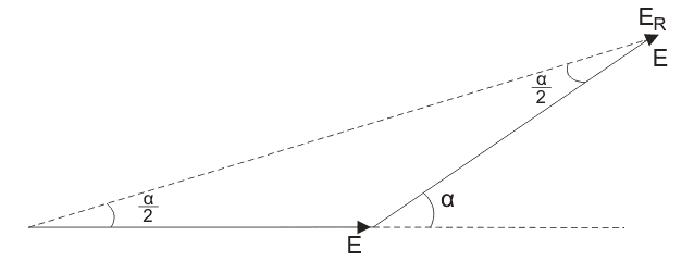
Now, as per definition of pitched factor,
This pitch factor is the fundamental component of emf. The flux wave may consist of space field harmonics also, which give rise to the corresponding time harmonics in the generated voltage waveform.
The 3rd harmonic component of the flux wave can be seen as produced by three poles instead of one, as in the fundamental component.
In the view of this, the chording angle for the rth harmonic becomes r times the chording angle for the fundamental component and pitch factor for the rth harmonic is given as,
The rth harmonic becomes zero, if,
In 3 phase alternator, the 3rd harmonic is suppressed by star or delta connection as in the case of 3 phase transformer. Total attention is given for designing a 3 phase alternator winding design, for 5th and 7th harmonics.
For 5th harmonic
For 7th harmonic
Hence, by adopting a suitable chording angle of α = 30o, we make most optimized design armature winding of alternator.
Distribution Factor
If all coil sides of one phase under one pole are grouped in one slot, it’s called a concentrated winding. The total induced emf is the arithmetic sum of the emfs from all coils of that phase under one pole.
But in practical cases, for obtaining smooth sinusoidal voltage waveform, armature winding of alternator is not concentrated but distributed among the different slots to form polar groups under each pole. In distributed winding, coil sides per phase are displaced from each other by an angle equal to the angular displacement of the adjacent slots. Hence, the induced emf per coil side is not an angle equal to the angular displacement of the slots.
So, the resultant emf of the winding is the phasor sum of the induced emf per coil side. As it is phasor sum, must be less than the arithmetic sum of these induced emfs.
Resultant emf would be an arithmetic sum if the winding would have been a concentrated one.
As per definition, distribution factor is a measure of resultant emf of a distributed winding in compared to a concentrated winding.
We express it as the ratio of the phasor sum of the emfs induced in all the coils distributed in some slots under one pole to the arithmetic sum of the emfs induced. Distribution factor is,
As pitch factor, distribution factor is also always less than unity.
Let the number of slots per pole is n.
The number of slots per pole per phase is m.
Induced emf per coil side is Ec.
Angular displacement between the slots,
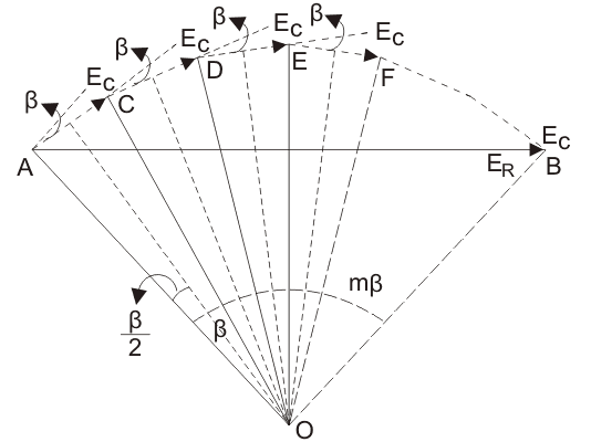
Let us represent the emfs induced in different coils of one phase under one pole as AC, DC, DE, EF and so on. They are equal in magnitude, but they differ from each other by an angle β.
If we draw bisectors on AC, CD, DE, EF ——–. They would meet at common point O.
Emf induced in each coil side,
As the slot per pole per phase is m, the total arithmetic sum of all induced emfs per coil sides per pole per phase,
The resultant emf would be AB, as represented by the figure,
Hence, the resultant emf
mβ is also known as the phase spread in electrical degree.
The distribution factor Kd given by equation is for the fundamental component of emf.
If the flux distribution contains space harmonics the slot angular pitch β on the fundamental scale, would become rβ for the rth harmonic component and thus the distribution factor for the rth harmonic would be.