

- Sequence Generator Definition: A sequence generator is a digital circuit that produces a specific sequence of bits.
- Purpose in Digital Electronics: Sequence generators are used to create specific patterns that do not follow standard counting orders, useful in various applications.
- Designing with D Flip-Flops: Sequence generators can be designed using D flip-flops, involving state transition and excitation tables.
- State Transition Table: This table outlines the present and next states, guiding the circuit’s operation.
- Boolean Expressions for Flip-Flops: Deriving Boolean expressions for flip-flop inputs helps in designing the sequence generator circuit.
We all know that there are counters which pass through a definite number of states in a pre-determined order. For example, a 3-bit up-counter counts from 0 to 7 while the same order is reversed in the case of 3-bit down counter. These circuits when suitably manipulated can be made to count till an intermediate level also. This means that instead of counting till 7, we can terminate the process by resetting the counter just at, say, 5. Such counters are then known as mod-N counters. However, even this case, the order in which they count will not alter. But, what-if if we need to through a specific pattern which does not adhere to this standard way of counting? The solution would be to design a sequence generator.
A sequence generator is a set of digital circuits designed to produce a specific bit sequence at their output. There are several ways to design these circuits, using multiplexers or flip-flops. This article focuses on designing a sequence generator using D flip-flops, although JK flip-flops can also be used.
For example, let’s design a circuit that cycles through the states 0-1-3-2 and then repeats. The steps to create this sequence generator are as follows.
Step 1
At first, we need to determine the number of flip-flops which would be required to achieve our objective. In our example, there are 4 states which are identical to the states of a 2-bit counter except the order in which they transit. From this, we can guess the requirement of flip-flops to be 2 in order to achieve our objective.
Step 2
Next, we write the state transition table for our sequence generator. The first two columns show the present states, and the next two columns show the next states. For example, the first state is 0 (00 in binary), which leads to the next state 1 (01 in binary), as shown in the gray-shaded row of Table I.
Step 3
We extend the state transition table to include the excitation table of the flip-flop we are using, which is a D flip-flop. The fifth and sixth columns of the table represent the excitation table of the D flip-flop.
For example, look at the orange shaded row in Table I in which the present and the next states 1 and 0 (respectively) result in D1 to be 0. The same row also shows the case wherein 
Table I
| Present States | Next States | Inputs of D flip-flops | |||
| Q1 | Q0 | Q1+ | Q0+ | D1 | D0 |
| 0 | 0 | 0 | 1 | 0 | 1 |
| 0 | 1 | 1 | 1 | 1 | 1 |
| 1 | 1 | 1 | 0 | 1 | 0 |
| 1 | 0 | 0 | 0 | 0 | 0 |
Step 4
Now its time to derive the Boolean expressions for D1 and D0. This can be done using any kind of simplification technique including K-map. However as our example is quite simple, we can just use the Boolean laws to solve for D1 and D0. Thus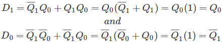
Step 5
Having known the inputs to either of the D flip-flops, now we can design our sequence generator as shown in this figure.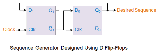
In the circuit shown, the desired sequence is generated based on the clock pulses supplied. At this point, it should be noted that, the analogy presented here for a simple design can be effectively extended to generate longer sequence of bits.