

- Flip Flop Definition: A flip flop is a basic digital memory circuit that stores one bit of data and can be used in various applications by connecting multiple flip-flops.
- Registers and Shift Registers: Registers store multiple bits of data using flip-flops, while shift registers move data within or out of registers based on clock pulses.
- Counters: Flip-flops form counters that count events and can be designed in various ways to suit specific counting needs.
- Event Detection: Flip-flops can detect events by changing states and holding the new state until the event is cleared.
- Frequency Division: Flip-flops can divide input frequencies by toggling their output states, effectively reducing the frequency by half for each flip-flop stage.
Registers
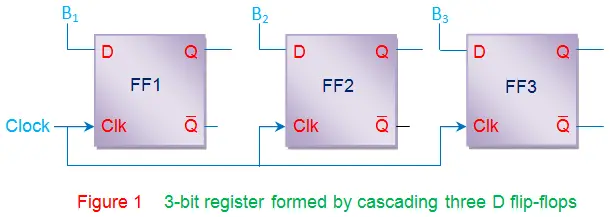
Registers are devices used to store data. Each v stores one bit of information. By connecting n flip-flops together, we can store n bits, forming an n-bit register. For example, three D flip-flops connected together can store three bits of information (B3, B2 and B1), creating a 3-bit buffer register.
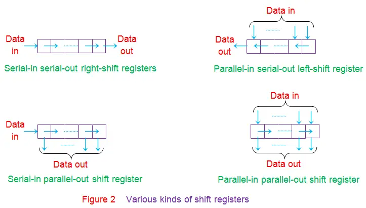
The data stored in the registers can be moved stage-wise within the registers and/or in/out of the register by applying clock pulses. Such a register is called shift register. There are various kinds of shift registers depending on the mode of data-shift viz., serial-in serial-out register, serial-in parallel-out register, parallel-in serial-out register, parallel-in parallel-out register. Further depending on the direction of data movement they can be either left-shift and/or right-shift in nature, as shown by Figure 2.
Counters
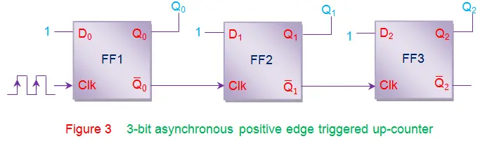
Counters are the digital circuits which are used to count the number of events. These are nothing but a series of flip-flops (JK or D or T) arranged in a definite manner. A single flip-flop has two states 0 and 1, which means that it can count upto two. Thus one flip-flop forms a 2-bit (or Modulo 2, MOD 2) counter. Similarly to count till 8, one needs to connect 3 (= 23) flip-flops in series as shown in Figure 3. These counters can either be synchronous/asynchronous and/or positive/negative edge-triggered depending on the connections provided at their clock inputs. Moreover by slightly modifying the connections between the flip-flops, various other kinds of counters can be designed viz., up-counter, down-counter, up/down counter, ring counter, johnson counter, etc.
Event Detectors
Event detectors help identify the occurrence of specific events. These circuits change state when an event occurs and hold that state until the event is cleared. Flip-flops are ideal for this because they maintain their state until a condition at their inputs changes. For example, a D flip-flop can detect when a light is switched on.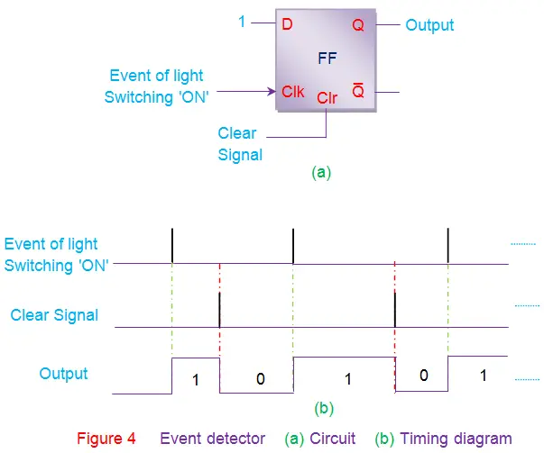
Data Synchronizers
Data Synchronizers ensure that all outputs of a combinational circuit change state simultaneously. Due to varying gate delays, outputs might change at different times, causing unexpected behavior and incorrect outputs. Using synchronous D flip-flops as data synchronizers can prevent this by making sure outputs change only with the clock signal.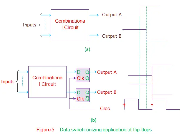
The flip-flops latch the outputs until the clock signal appears. The outputs can only change state when the positive edge of the clock triggers the flip-flops, ensuring all outputs change simultaneously.
Frequency Divider
Consider a positive edge triggered JK flip-flop whose inputs are tied-together and driven high, as shown in Figure 6. In this state, the output of JK flip-flop will toggle for each positive-edge of the clock signal (red lines in the figure). From the waveform it is evident that if the input clock period is Tin, then the time period of output waveform Tout is twice of it. Thus one gets fout = fin/2 which implies that input frequency is divided by 2. In other words, after passing through a single flip-flop, the input frequency will be halved. On the same grounds one can conclude that after passing through the n flip-flops, the input frequency will be divided by 2n which results in fout = fin/2n.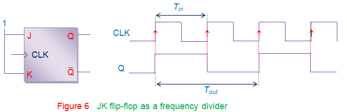
Apart from these applications, a few flip-flops have definite uses like
- D flip-flop can be used to create delay-lines which are used in digital signal processing systems. This application arises readily due to the fact that the output at the synchronous D flip-flop is nothing but the input delayed by one-clock cycle. Thus by cascading n such flip-flops, output can be delayed by n clock cycles which in turn produces the required amount of delay.
- Generally the mechanical switches used to enter the values into the digital system are prone to bouncing problem where the switch-contacts vibrate while closing/opening the switch. This leads to the variation in the output voltage causing the logical inputs to alternate between 0 and 1. This results in unexpected system behavior which can be avoided by connecting a RS flip-flop between the switch and the digital circuit to act as a switch debouncer.