

- Parallel Subtractor Basics: A parallel subtractor is a circuit used to subtract n-bit binary numbers efficiently by handling multiple bits simultaneously.
- Using 2’s Complement: Subtraction in a parallel subtractor involves converting the subtrahend to its 2’s complement and then adding it to the minuend using binary addition techniques.
- Circuit Design: The n-bit parallel subtractor can be designed using a series of full adders, where the first adder’s carry-in is set high to handle the 2’s complement addition.
- Comparison with Parallel Adder: Like a parallel adder, the parallel subtractor can suffer from ripple propagation, affecting the timeliness and accuracy of its output.
- Practical Applications: Understanding the function and design of parallel subtractors is crucial for designing efficient digital systems that perform quick arithmetic operations.
Subtractors are combinatorial circuits designed to subtract two binary numbers. For single-bit binary numbers, a half subtractor suffices. When subtracting three single-bit numbers, two inputs and a borrow, a full subtractor is necessary. For two n-bit binary numbers, an n-bit parallel subtractor is used.
Structure of Parallel Subtractor
Generally when one needs to subtract the binary number 2 from binary number 1, then the binary number 2 will be expressed in its 2’s complement form and then added with the binary number 1 (nothing but 2’s complement form of binary subtraction).
Next, 2’s complement of a number can be obtained by taking 1’s complement of the number and then by adding 1 to its least significant bit (LSB). Further, taking 1’s complement means nothing but negating the binary number.
From the discussion presented, one can conclude that inorder to accomplish subtraction, one can use the same circuit as that for addition (more on this in the article “Parallel Adder”) provided we have the number ‘to be subtracted’ in its 2’s complement form. This task of expressing the number in 2’s complement form may be brought about by first using NOT gates to invert the bits in the binary number. However, to add 1 at LSB, one can make use of the first adder in the sequence of n full adders used in the circuit just by providing logic high at its carry in (Ci1) pin. As a result, one can design the n-bit parallel subtractor as shown in Figure 1.
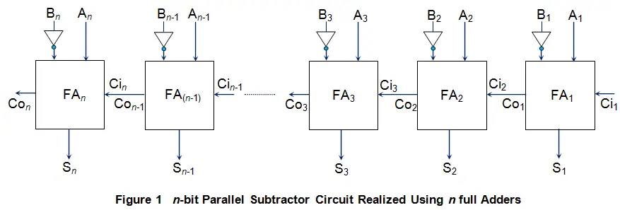
Here the binary number  is the minuend and the binary number
 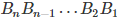 is the subtrahend. Further, the sum outputs of each and every adder actually correspond to the difference bits (the expected result) while the carry out pin of the last full adder (Con) will be nothing but the resultant borrow.
Apart from this kind of circuit, one can even design the parallel subtractor using just a cascaded array of full subtractors. Figure 2 shows such an-bit parallel subtractor designed using n full subtractors (FS1 to FSn) joined in a way similar to that of in the case of n-bit parallel adder.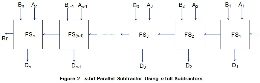
The working of such a circuit is straight forward and is very similar to that of a parallel adder. As a result, even parallel subtractors are prone to the effect of ripple propagation which results in the delayed output. That is, if the dealy associated with each of the full subtractor is T seconds, then the overall difference bits (D1D2…Dn) and borrow bit (Br) are obtained only after n T seconds.