- Binary Adder Definition: A binary adder is defined as a combinational logic circuit that adds binary numbers, producing a sum and a carry.
- Half Adder Definition: A half adder is defined as a circuit that adds two single-bit binary numbers, outputting a sum and a carry bit.
- Full Adder Definition: A full adder is a logic circuit that adds three binary bits, including a carry bit, resulting in a sum and a carry output.
- Binary Full Adder Operation: The binary full adder adds two binary digits and an incoming carry bit, crucial for multi-bit binary addition.
- Binary Parallel Adder: A binary parallel adder connects multiple full adders to add binary numbers with multiple bits simultaneously.
A binary adder is one of the basic combinational logic circuits. Its outputs depend only on the current inputs, not on any previous inputs. This means it doesn’t need memory components. Binary adders are fundamental because they only use the current state of input variables.
Designing Binary Adder
Half Adder
Before designing a binary adder, we need to understand some basic rules of binary addition. The simplest form of binary addition is adding two single-bit binary numbers.
The binary digits are 0 and 1. Hence, there must be four possible combinations of binary addition of two binary bits
In the list, the first three binary operations result in one bit, but the fourth results in two bits. If both binary digits are 1, the sum will have two digits: the higher significant bit (HSB), or left-side bit, called the carry, and the lower significant bit (LSB), or right-side bit, called the sum bit. The circuit performing this one-bit binary addition is called a half adder.
Design of Half Adder
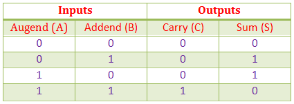
For designing a half adder logic circuit, we first have to draw the truth table for two input variables i.e. the augend and addend bits, two outputs variables carry and sum bits.
In first three binary additions, there is no carry hence the carry in these cases are considered as 0.
Truth Table for Half Adder
K-map for Half Adder
Now from this truth table we can draw K-map for carries and sums separately.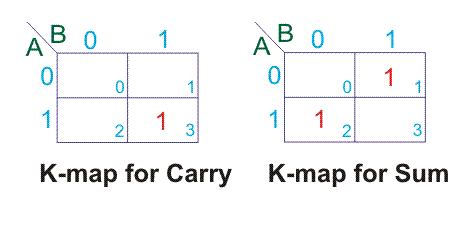
For above K-maps we get,
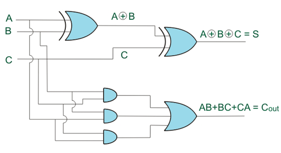
Hence, the logical design of Half Adder would be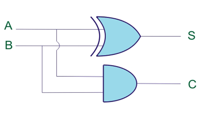
Although from truth table it is clearly seen that carry (C) column signifies AND operation and sum (S) column signifies XOR operation between input variables but till we went through K-map as it is general practice to do so for more complex binary logic operations.
Full Addition
Before knowing about full adder, let us know what is full addition? For that let us consider the example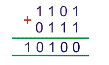
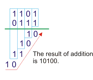
There, are two four bits binary numbers 1101 and 0111 which we have to add. The process of binary addition is like follows,
- We have to add first list significant bit (LSB) of both 4bits binary number first and this will result a two bits binary number.
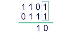
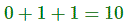
Here, LSB of 1101 and 0111 are 1, hence 1 + 1 = 10. The LSB of 10 is 0 and higher significant bit (HSB) is 1. - The LSB of the result is sum and to be put at the list significant position of the final result of the sum, and HSB of the two bits results will be carry and to be added with next higher significant bit of two 4bits augend and addend are 0 and 1 and the carry of previous result i.e. 1 to be added with 0 and 1.
- After this addition, that is next higher than list significant bit of bits of both binary augend and addend and it is previous carry we get another two bits result. This also has carry and sum. Here also we will write sum at final result and add the carry to the next higher significant bits of augend and addend. This will continue up to most significant bit of augend and addend.
Full Adder
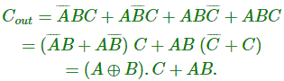
A full adder is a circuit that performs full binary addition, meaning it adds two bits and an incoming carry bit, then outputs a sum bit and a carry bit.
Any bit of augend can either be 1 or 0 and we can represent with variable A, similarly any bit of addend we represent with variable B. The carry after addition of same significant bit of augend and addend can represent by C. Hence truth table for all combinations of A, B and C is as follows,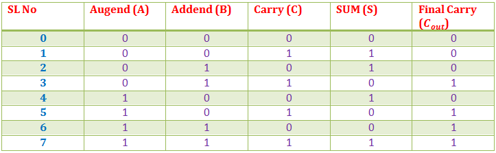
From the above table, we can draw K-map for sum (s) and final carry (Cout).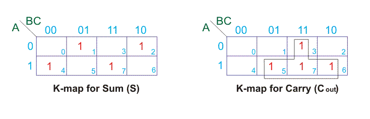
Hence, from K-maps,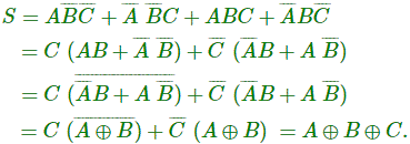

Binary Parallel Adder
A full binary adder adds single bits of two binary numbers and a carry from the previous addition. However, a single full adder can’t add multi-bit numbers at once. By connecting multiple full adders, we can add binary numbers with more bits. This setup is called a binary parallel adder. To add two 4-bit binary numbers, we need to connect 4 full adders to create a 4-bit parallel adder.
The inter connection of 4 full adder in 4bit parallel adder is shown below,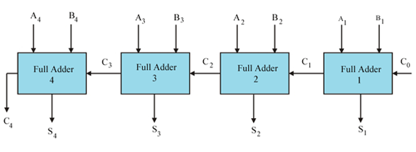
Let us examine the justification of the above circuit by taking an example of addition of two 4 bit binary numbers.
Let us add 1011 with 1101.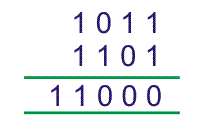
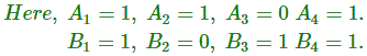
As there is no previous carry C0 = 0.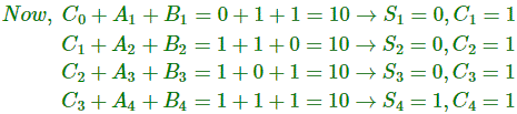
Therefore, final result of the addition would be
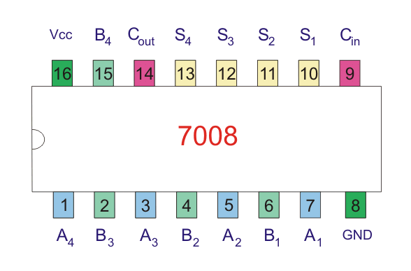
There are 1 bit, 2 bits and 4 bits parallel adders ICs commercially available in market. For n bit parallel adder required number of such ICs are connected together.
4 bit parallel adder IC is 4008. In n bit parallel adder, output carry terminal of one IC would be connected with input carry terminal of next IC.