

- Digital Counter Definition: A digital counter is defined as an electronic circuit used to count occurrences of events.
- Flip-Flops: Flip-flops, like D and JK types, are the building blocks of digital counters.
- Types of Counters: Counters can be asynchronous, synchronous, up, or down, based on their clock inputs and counting direction.
- Synchronous Counters: Synchronous counters have all flip-flops driven by the same clock pulse to avoid delays.
- Special Counters: Counters such as Ring, Johnson, and Mod-N have unique counting sequences, providing various functionalities.
A counter is defined as an electronic circuit that counts how many times an event happens. In digital electronics, counters are made using flip-flops, especially D and JK flip-flops types.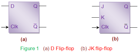
As known, flip-flops are bi-state devices, meaning they have two states, either zero (0) or one (1). Thus a single flip-flop can track a count of two i.e. it counts from 0 to 1 and hence called modulo-2 (mod-2) counter.
On the same grounds one can expect two flip-flops connected in series to form 2-bit counter counting from 0 to 3 comprising of 4 states and hence can be referred to as mod-4 counter. Generalizing, one gets n-bit or mod-n counter of 2n states counting from 0 to (2n-1) by cascading n flip-flops. However to behave as counters, flip-flops must be driven by high (logic state 1) at their inputs, both in case of D as well as JK-types. The reason behind this can be understood by the truth tables given by Table I.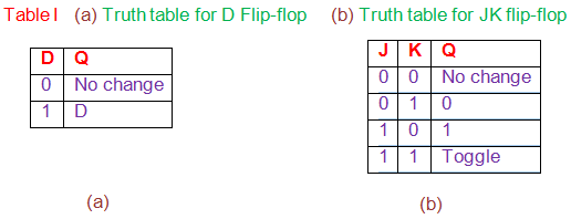
Considering D flip-flop, it can be seen that the output changes only when the input is high. Similarly for JK flip-flop output state remains either unchanged (for J = K = 0) or fixed to a particular value (0 for J = 0 and K = 1; 1 for J = 1 and K = 0) for all cases expect when both of them are high. In counters the state is expected to change and not to remain tied-up to a particular value. Hence when ‘1’ is driven on the inputs of these flip-flops, they act as 1-bit counters (Figure 2).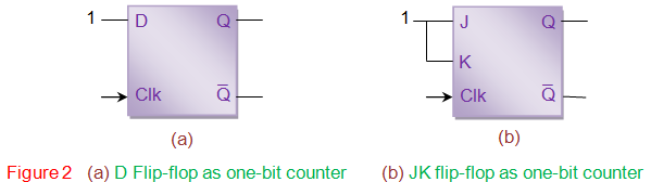
The characteristics of the counter are determined by the mode of interconnection between the flip-flops. Counters can be
- Asynchronous or Synchronous,
- Up or Down-counters and/or
- Positive or Negative edge triggered depending on the connection provided at the clock input of the flip-flops. The behaviour of a counter can be explained interms of timing diagram (waveforms), truth table and/or state diagrams.
Figure 3 shows a 3-bit asynchronous up-counter formed by cascading three positive-edge triggered D flip-flops. Here all inputs (D0, D1 and D2) are made high. Clock input of flip-flop 1 (FF1) is driven by external clock pulses while those of the second and third (FF2 and FF3) are driven by  respectively. Here the operation of FF1 is dependent on external clock pulse train while those of FF2 and FF3 depend on . This is in accordance with the fact that the working of flip-flops depend on the clock input.
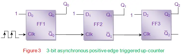
Let us assume that the initial state of the counter is Q2Q1Q0 = 111, just for the sake of understanding the working of counter. In this case, for the first clock pulse Q0 bit toggles from 1 from 0. This implies that the  bit toggles from 0 to 1 which further acts as a positive clock pulse for FF2 (indicated by red arrow in Figure 4), changing its output bit Q1 from 1 to 0. This inturn toggles Q2 bit from 1 to 0 as it is triggered by the transition of
  bit from 0 to 1. Thus for the first clock pulse, the output of the counter will be 000.
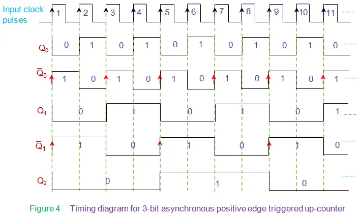
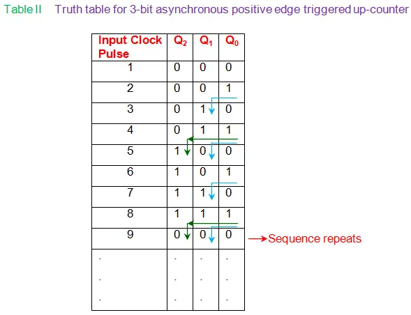
Then for the leading edge of the second clock pulse Q0 again toggles from 0 from 1 which implies bit toggles from 1 to 0. This acts like a trailing edge and hence there is no change in the state of FF2, which causes Q1 to remain at 0. Due to the unchanged state of FF1, state of FF3 also remains the same which yields Q1 = Q2 = 0. Thus we have 001 as the output of the counter. Following on the same grounds, one can see that for the third clock pulse Q0 = 0 and = 1. Thus one can notice state transitions in FF2 which yields Q1 = 1 and = 0. However the output of the FF3 remains low as there is no positive transition of the signal at its clk pin. This yields the counter output as 011. The behavior of flip-flops at clock pulse 4 is analogous to that of clock pulse 2, except that the state of output bits which is 100 for this case. At fifth clock pulse, Q0 = 0 (hence = 1); Q1 = 0 (hence = 1). The transition of from 0 to 1 triggers FF3 to change its state from 0 to 1 which results in 101 at the output of the counter. For further clock pulses the output of the counter can be obtained on the same basis. However after 8th clock pulse, sequence repeats as shown by the state diagram of Figure 5 and truth table given by Table II.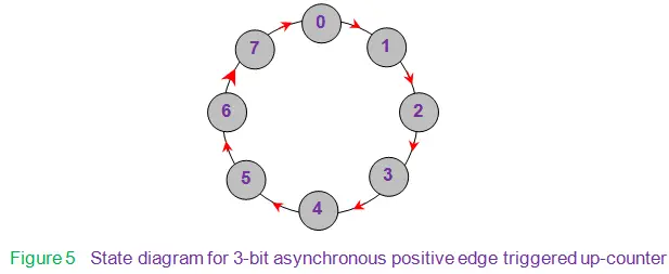
In general we see that for a n-bit counter resembling the one in Figure 3, lower most bit (LSB) = 2o toggles for every clock cycle, while the next higher bits toggle only when their preceding bits change their state from 1 to 0. For example, Q2 bit in the 3-bit up-counter changes its state only when Q1 bit changes from 1 to 0 (which is nothing but changing from 0 to 1 in Figure 4). This can be viewed as though a ripple propagates through the arrangement of flip-flops and thus counters are called ripple counters. Moreover here all the flip-flops will not be triggered simultaneously. Hence they are asynchronous in nature.
The ripple effect in asynchronous counters can cause delays due to flip-flop propagation. To solve this, synchronous counters use the same clock input for all flip-flops, ensuring they change state simultaneously and avoid delays.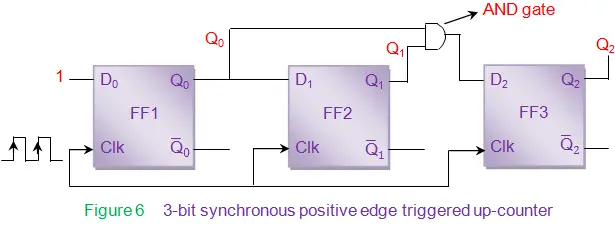
From Figure 6, it is seen that all the flip-flop inputs are not driven high as in the case of asynchronous counter (Figure 3). For synchronous counters, connections to the input pins of the flip-flops (D0 of FF1, D1 of FF2 and D2 of FF3) are decide depending upon the sequence of states expected by the counter. As the counter shown in Figure x is analogous to its counter-part shown in Figure 3, the number of states and the transition between the states remains the same. Hence the state diagram and the truth table remain unaltered. Thus the drive for the input bits can be arrived at by analyzing Table II to find the conditions required for the output bits to toggle.
As evident from the table, bit Q0 is required to toggle for every positive edge transition on the input clock pulse. Hence the input pin D0 is to be driven high. However bit Q1 needs to transit only when the bit Q0 is 1, indicated by blue arrows in Table II. This can be achieved by connecting Q0 as the input to FF2. Further it is also noticed that Q2 has to change its state only if both Q1 and Q0 are high as shown by green arrows in Table II. In order to achieve this condition, one needs to make use of two input AND gate driven by the bits Q0 and Q1. This is due to the fact that the output of the AND gate is high only when all of its inputs are high. Now the counter shown in Figure 6 works as an up-counter counting from 0 to 7 incrementing by one for each input clock pulse.
In general, in a n-bit synchronous up-counter the LSB is required to toggle for every positive edge transition on the input clock pulse; the next higher bit needs to change its state only when its preceding bit (= LSB) is high; the very next higher bit has to transit only if both of its preceding bits are high and so on. Thus in case of synchronous counter the flip-flops change their state only when the outputs of all the preceding flip-flops are high. In order to achieve this, one has to connect the output of AND gates to drive the input pins of each flip-flop. Further at each stage these AND gates are required to logically ‘and’ the output bits of all the previous flip-flops.
The working of down-counters is almost similar to that of up-counters except the fact that the sequence of counting will be from high to low decrement by one for each clock pulse. or example, 3 bit down-counter counts from 7 (111) to 0 (000) and not from 0 to 7. Thus in case of asynchronous counter one has to consider the transition of output bits from 0 to 1 instead of 1 to 0. Similarly in case of synchronous counters AND gates are to be used to logically ‘and’  bits instead of Q bits.
Other than the basic up and down-counters, other special types of counters also exist like Ring Counter, Johnson Counter, Decade Counter, Mod-N counter and so on. Moreover slight modifications to the proposed counter design would yield variations like
- Adding a control line to select either up or down counting leads to realize an up/down counter,
- Usage of clear and preset pins of the flip-flops allows one to set initial state for the counter
- Addition of suitable logic leads to break the sequence of counting before 2n states have elapsed i.e, a 3 bit counter can be made to count only till 5 and can be made to repeat the sequence (Mod-6 counter). However it is to be noted that although the design for each of these differs by certain amount, basic principle of working behind all of them remains the same.