

- Zener Diode Definition: A zener diode is defined as a diode with a low breakdown voltage that can operate in reverse bias to maintain a constant voltage.
- Voltage Regulation: Zener diodes are used as voltage regulators to provide a stable output voltage despite input voltage variations.
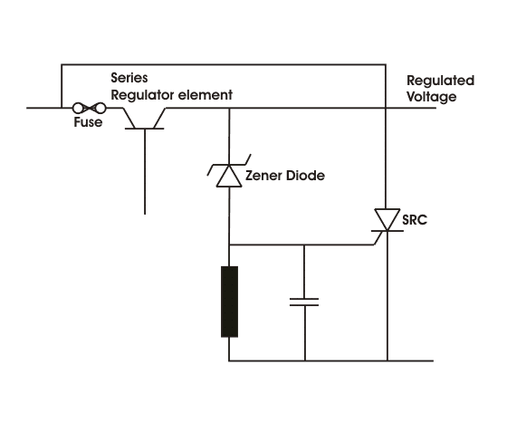
- Meter Protection Principle: The principle of zener diode in meter protection involves using zener diodes to shunt excess current and protect meters from overloads and polarity reversals.
- Wave Shaping: Zener diodes can convert sinusoidal waveforms into square waves by clipping the input waveform at specific voltage levels.
- Advantages and Limitations: Zener diodes are simple and inexpensive but have limitations like inefficiency, limited current capacity, and potential signal distortion.
A zener diode is a special type of diode that can operate in reverse bias mode and maintain a constant voltage across its terminals. Zener diodes are widely used in electronic circuits for various purposes, such as voltage regulation, meter protection and wave shaping. In this article, we will explain the basic principle and operation of zener diodes and their applications in detail.
What is a Zener Diode?
A zener diode is defined as a diode that has a breakdown voltage (also called zener voltage) lower than the normal breakdown voltage of a conventional diode. A breakdown voltage is the minimum reverse voltage that causes a diode to conduct a large current in the opposite direction. A conventional diode has a high breakdown voltage (usually tens or hundreds of volts) and is designed to prevent reverse current flow. A zener diode has a low breakdown voltage (usually less than 10 volts) and is designed to allow reverse current flow when the reverse voltage exceeds the zener voltage.
The zener voltage of a zener diode depends on the doping level and the thickness of the p-n junction. Doping level refers to the amount of impurities added to the semiconductor to create charge carriers (electrons and holes). The p-n junction thickness is the distance between the p-type and n-type regions. Lower doping levels and thicker p-n junctions result in higher zener voltages.
There are two mechanisms that cause reverse breakdown in zener diodes: zener effect and avalanche effect. The zener effect occurs at low voltages (below 5 volts) and involves quantum tunneling of electrons across the narrow p-n junction. The avalanche effect occurs at high voltages (above 5 volts) and involves impact ionization of charge carriers due to high electric field across the wide p-n junction. Both effects are present in zener diodes, but one dominates depending on the zener voltage.
The forward voltage across the zener diode is less than 0.7 volts (the typical value for silicon diodes), it behaves like a normal diode and conducts a small forward current. When the forward voltage exceeds 0.7 volts, it behaves like a short circuit and conducts a large forward current.
When the reverse voltage across a zener diode is less than its zener voltage, it acts like an open circuit, blocking any reverse current. When the reverse voltage reaches or exceeds the zener voltage, it acts like a constant voltage source, maintaining a steady reverse current. This current depends on the external circuit resistance and can range from microamps to milliamps.
The advantage of using a zener diode as a constant voltage source is that it can provide a stable output voltage regardless of variations in input voltage or load resistance, as long as the input voltage is higher than the zener voltage and the load current is within the maximum rating of the zener diode.
Zener Diode as Voltage Regulator
One of the most common applications of zener diodes is as a voltage regulator or stabilizer. A voltage regulator is a device that provides a constant output voltage to a load from an input source whose voltage may vary over a wide range.
In this circuit, R S is a series resistor that limits the current through the zener diode, R L is the load resistor that represents the device or circuit that needs a constant voltage supply, V S is the input source voltage that may fluctuate over time, and V O is the output voltage across R L that should be equal to V Z ,the zener voltage of D Z .
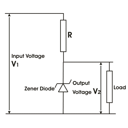
The operation of this circuit can be explained as follows:
- When V S is less than V Z , no current flows through D Z and V O = V S . The output voltage follows the input voltage until it reaches V Z .
- When V S is equal to V Z , D Z starts to conduct in reverse bias mode and V O = V Z . The output voltage becomes equal to the zener voltage and remains constant.
- When V S is greater than V Z , D Z conducts more current in reverse bias mode and V O = V Z . The output voltage remains equal to the zener voltage while R S absorbs the excess input voltage (V S – V Z ) as heat.
The value of R S can be calculated from Ohm’s law as:
R S = (V S – V Z ) / I Z
where I Z is the minimum current required for D Z to operate in reverse breakdown mode. This value can be obtained from the datasheet of D Z . The value of R S should be chosen such that it can handle the maximum power dissipation without overheating.
The advantages of using a zener diode as a voltage regulator are:
- It is simple, cheap and easy to implement.
- It can provide a wide range of output voltages by choosing different values of V Z.
- It can provide good regulation for low-power applications.
The disadvantages of using a zener diode as a voltage regulator are:
- It has poor efficiency due to power loss in R S .
- It has poor load regulation due to changes in I Z with changes in R L .
- It has poor line regulation due to changes in I Z with changes in V S .
- It has limited output current capacity due to a maximum rating of D Z.
Zener Diode as Meter Protector
Another application of zener diodes is as a meter protector. A meter protector is a device that protects an electrical meter (such as an ammeter, voltmeter, or ohmmeter) from damage due to accidental overloads or polarity reversals. A meter protector usually consists of one or more zener diodes connected in parallel with the meter movement.
In this circuit, M is an ammeter that measures current I flowing through R L , D 1 and D 2 are two identical zener diodes with zener voltages equal to half of the maximum allowable meter deflection (V M ), R S1 and R S2 are two series resistors that limit the currents through D 1 and D 2 respectively.
The operation of this circuit can be explained as follows:
- When I < V M / R M, where R M is the internal resistance of M, no current flows through D 1 or D 2, and M normally deflects according to Ohm’s law.
- When I > V M / R M, either D 1 or D 2 starts to conduct depending on the polarity of I. For example, if I > 0, then D 2 conducts while D 1 blocks. This causes most of I to bypass M through D 2 while only I M = V M / R M flows through M. This limits the meter deflection to V M while protecting M from overload damage.
- When I < -V M / R M, then D 1 conducts while D 2 blocks. This causes most of I to bypass M through D 1 while only I M = -V M / R M flows through M. This limits the meter deflection to -V M while protecting M from polarity reversal damage.
The advantages of using a Zener diode as a meter protector are:
- It is simple, cheap, and easy to implement.
- It can protect meters from both overloads and polarity reversals.
- It can work with both AC and DC currents by using two identical zener diodes.
The disadvantages of using a Zener diode as a meter protector are:
- It introduces some errors in meter readings due to the nonlinearity of D 1 and D 2.
- It reduces meter sensitivity due to the shunting effect of D 1 and D 2.
- It requires a careful selection of values for V Z, R S1, and R S2.
Zener Diode as Wave Shaper
A third application of zener diodes is as a wave shaper. A waveshaper is a device that modifies an input waveform into another waveform with different characteristics. A waveshaper usually consists of one or more nonlinear elements such as resistors, capacitors, inductors, or diodes.
In this circuit, C is a capacitor that blocks DC components while passing AC components, R L is a load resistor that represents the device or circuit that needs a square wave input, V S is a sinusoidal source with peak amplitude greater than the more zen voltage, and V O is the output voltage across R L that should be a square wave.
The operation of this circuit can be explained as follows:
- During the positive half-cycle of V S, when the voltage across D1 and D2 is less than the zener voltage, they offer high resistance and block current flow. The input voltage appears across the output terminals unchanged.
- When the positive peak of V S exceeds the more zen voltage, D 1 starts to conduct in reverse bias mode and clamps the output voltage to V Z . The excess voltage (V S – V Z ) is dropped across R S.
- During the negative half cycle of V S, when the voltage across D 1 and D 2 is less than the more zen voltage, they offer a high resistance path and block any current flow. The input voltage appears across the output terminals as it is.
- When the negative peak of V S exceeds the more zen voltage, D 2 starts to conduct in reverse bias mode and clamps the output voltage to -V Z . The excess voltage (-V S + V Z ) is dropped across R S.
The advantages of using a zener diode as a wave shaper are:
- It is simple, cheap, and easy to implement.
- It can convert sine waves into square waves with adjustable amplitude by choosing different values of V Z.
- It can work with both AC and DC input voltages by using two identical zener diodes.
The disadvantages of using a Zener diode as a wave shaper are:
- It introduces some distortion and noise in the output waveform due to the non-linearity of D 1 and D 2.
- It reduces the input signal amplitude due to the clipping effect of D 1 and D 2.
- It requires careful selection of values for V Z, R S, and C to ensure proper operation and stability.
Conclusion
Zener diodes are versatile devices that can be used for various applications in electronic circuits. They can provide a constant and stable output voltage from a variable input source, protect meters from overloads and polarity reversals, and modify input waveforms into different shapes. Zener diodes are available in different ratings and packages to suit different needs and preferences. They are easy to use and require minimal external components. However, they also have some limitations and drawbacks that need to be considered before using them.