

- Voltage Doubler Definition: A voltage doubler is an electronic circuit that generates an output voltage twice as high as its input voltage.
- Circuit Design: Voltage doublers utilize two capacitors and two diodes in a setup that converts AC input to a higher DC output.
- Half-Wave Operation: In half-wave doublers, each capacitor charges during alternate half-cycles of the AC input, blocked from discharging by diodes, to provide double the input voltage.
- Full-Wave Benefits: Full-wave voltage doublers charge capacitors during both cycles of AC, offering a more stable output voltage under no-load conditions.
- Practical Applications: Voltage doublers are essential in devices requiring high voltages, such as ion pumps and X-ray systems, due to their efficiency in stepping up voltage.
What is a Voltage Doubler?
A voltage doubler is an electronic circuit that produces an output voltage that is double the input voltage. It is a voltage multiplier with a voltage multiplication factor equal to 2. The circuit is formed by an oscillating AC input voltage, two capacitors, and two diodes. The input voltage is AC, and the output is DC voltage with twice the peak value of the input AC voltage.
Voltage doublers can substitute for bulky and costly step-up transformers in various applications.
There are two main types of voltage doublers: half wave voltage doublers and full wave voltage doublers.
Types of Voltage Doubler
Half Wave Voltage Doubler
The figure below shows a simple DC voltage doubler circuit. Here, it is clear that both the capacitors and the diodes operate together to create the double voltage output.
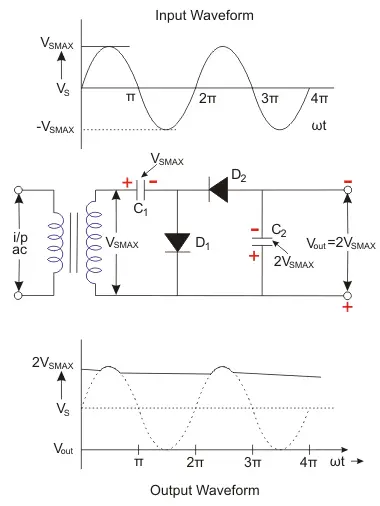
Now, we can go through the working of the half-wave DC voltage doubler. All over the positive half cycle of the AC sine wave, the first diode (D1) is conducting.
That is a forward biased state, and it will charge the connected capacitor (C1) equal to the peak value of AC secondary voltage of transformer (VSMAX).
This capacitor is unable to get discharged due to the unavailability of a path. So, it will remain in a fully charged condition.
Next, all over the negative half cycle, the second diode (D2) is conducting or forward biased state, and the first diode (D1) is non-conducting or in the reversed biased state.
The reversed biased diode (D1) will block the discharging of the connected capacitor (C1), and the forward-biased diode (D2) will charge the connected capacitor (C2).
Kirchhoff’s voltage law is applied to the outer loop of the transformer, starting at the negative lower end and moving clockwise to the positive top end.

The voltage across capacitor C2 equals twice the peak value of the transformer’s secondary input voltage, or (2VSMAX).
Throughout the next positive half cycle of AC input, the second diode (D2) will be open due to the reversed biased condition. So, the second capacitor (C2) will get discharged through the load and the output voltage (Vout) < 2VS MAX.
Otherwise, the two capacitors will be in the charged condition as said above. If there is a load, then in the next cycle, the C2 will get recharged again.
Full Wave Voltage Doubler
In the full-wave voltage doubler, the components are the same as that of half-wave voltage doubler. But difference is in the circuit, as shown below.

In this doubler, right through the positive cycle of input AC voltage, the first diode (D1) is in the conducting state.
That is a forward biased state, and it will charge the connected capacitor (C1) equal to the peak value of AC secondary voltage of transformer (VSMAX).
At this time, D2 will be in reverse biased condition or non-conducting state. Throughout the negative cycle of input AC voltage, the second diode (D2) will be in forwarding biased state, and the second capacitor (C2) gets charged.
In the no-load condition, the entire voltages of two capacitors  are delivered as the output voltage.
When a load is connected across the output terminals, the output voltage (Vout) may be less than 2VS MAX.

We can observe that both the voltage doubler will provide 2VS MAX as the output. There is no need for a centre-tapped transformer. 2VS MAX will be the peak inverse voltage ratings of the circuit diodes.
Advantages of Voltage Doubler
Voltage doublers offer several advantages:
- Can replace the expensive and heavy transformers.
- Negative voltage can also be created by reversing the polarity of the connected diodes and capacitors.
- Can increase the voltage multiplication factor by cascading the similar voltage multipliers.
Application of Voltage Doubler
The applications of voltage doublers include:
- Ion pumps
- Television CRT
- X-Ray systems
- Copy machine
- Radar equipment
- Travelling wave tubes etc