

- Bistable Multivibrator Definition: A bistable multivibrator is defined as a circuit that switches between two stable states using external triggers.
- Other Names: It is also called a trigger circuit, Eccles-Jordan circuit, scale-of-2 toggle circuit, binary, or flip-flop.
- Working Principle: The circuit operates with two NPN transistors, where one turns off while the other turns on, switching states with an external trigger.
- Triggering Methods: Bistable circuits rely on external triggers, which can be asymmetric (independent sources) or symmetric (same type for both transistors).
- Applications: These circuits are used in various applications, including memory storage, timing circuits, and frequency dividers.
Bistable Multivibrators are the multivibrators which depend upon the external triggers so as to switch between their two permissible stable states. These circuits are also referred to as Trigger Circuits or Eccles Jordon Circuits or Scale-of-2 Toggle Circuits or Binary or more popularly as Flip-Flops, forming the basic building blocks of sequential digital systems. These circuits can be designed in different ways, say for example, they can compose of transistors or Op-Amps or 555 timer ICs along with passive components, the resistors. Figure 1 shows such a circuit designed using two NPN bipolar junction transistors (BJTs) Q1 and Q2 and four resistors RC1, RC2, R1 and R2.
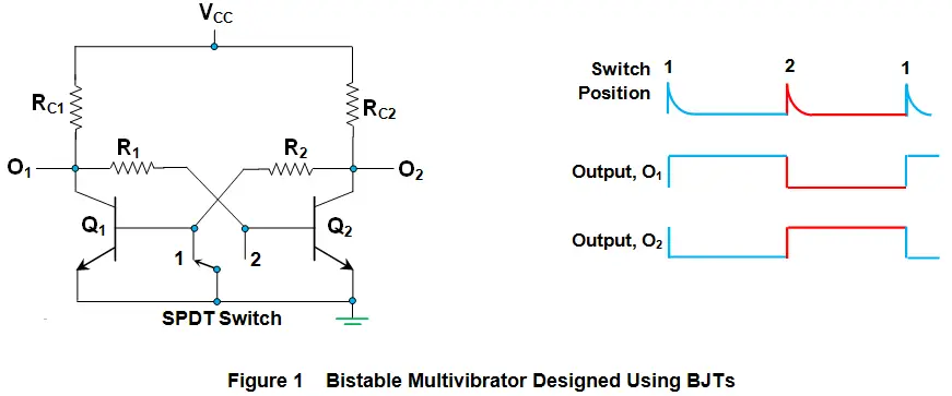
Initially, when the SPDT switch is in position 1, it grounds the base of transistor Q1. This turns Q1 off (cutoff region) and its collector goes to VCC, making the output at Q1 high. This forward biases the base-emitter junction of transistor Q2, turning it on (saturation mode). As a result, current flows through RC2, grounding the collector of Q2. Thus, the output at Q2 goes low.
This state remains unchanged until an external trigger occurs. Changing the switch from position 1 to 2 acts as the trigger. This grounds the base of Q2, turning it off (cutoff region). The collector of Q2 goes to VCC, making the output at O2 high. At the same time, Q1 turns on (saturation mode) as its base is connected to the collector of Q2 via R2. This grounds the collector of Q1, making the output at O1 low. This state continues until triggered again.
From the explanation presented, the following two points can be concluded on the nature of the bistable circuits.
- Bistable circuits are not self-triggered as they rely on the user-provided trigger inputs so as to change their state.
- In these circuits, the output wave-forms obtained at the terminal O1 and O2 are complementary to each other, always.
Triggering a bistable circuit is easier electronically than mechanically. This can be asymmetric (separate triggers for each transistor) or symmetric. Symmetric triggering can be base, collector, or hybrid.
Bistable circuits are used in memory storage devices, timing circuits, frequency dividers, toggle switches, counting circuits, shift registers, clock pulse generators, relay controllers, and radar communications.