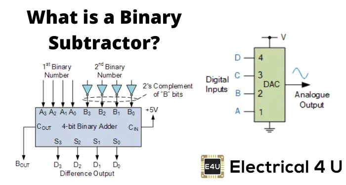
- Binary Subtractor Definition: A binary subtractor is a digital circuit used to subtract two binary numbers and provides outputs of the difference and potential borrow.
- 2’s Complement Subtraction: This essential subtraction method involves inverting the bits of the subtrahend, adding one, and then adding it to the minuend to calculate the difference.
- 4 bit subtractor: A 4 bit subtractor specifically handles subtraction of binary numbers up to four bits in length, simplifying the operation by directly addressing each bit.
- Half vs. Full Subtractor: A half subtractor subtracts single bits and provides a difference and borrow, whereas a full subtractor extends this functionality to multi-bit binary numbers.
- Circuit Complexity: Understanding the use of logic gates and K-maps in subtractors helps clarify how subtractors are designed to manage binary subtraction efficiently.
Before discussing about binary substractor, let us discuss about method of substracting two multi bit binary numbers.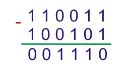
For above substraction we used general rules which are,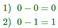
and borrow 1 which to be added to next higher significant bit of first binary number. Then same positioned bit of second binary number would be substracted from that.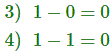
But there are other methods by which two binary numbers can be substracted confidently. One of these is 2’s complement method of substraction.
In the 2’s complement subtraction method, we keep the first binary number unchanged. Each bit of the second binary number is then inverted, and 1 is added to the least significant bit (LSB) of this inverted number. This forms the 2’s complement of the second number. Adding this complement to the first number yields the subtraction result.
Here in the previous example,
First binary number was 110011 and second binary number was 100101. Complement or 1’s complement of 100101 is 011010. Now by adding 1 with LSB of this 1’s complement number we get,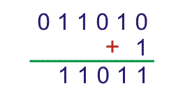
Now by adding first number, 110011 and 2’s complement of second number i.e. 11011. We get,
Hence, 4 bit substractor can be drawn like,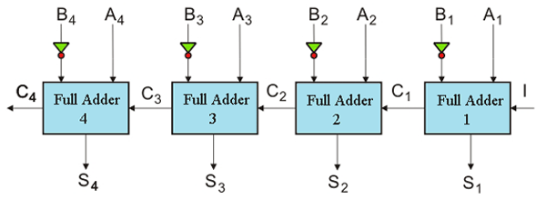
Here, A4, A3, A2, A1 is minuend and B4, B3, B2, B1 is subtrahend. S4, S3, S2, S1 is result of substraction where C4 is final carry which is ignored.
Half Substractor
A half subtractor is a type of combinational circuit designed to subtract single-bit binary numbers. It evaluates all possible subtraction combinations between two single bits.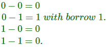
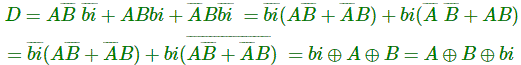
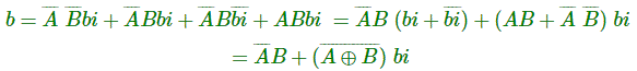
Now if we draw a truth table for that, with all differences (D) and borrow (b), we get,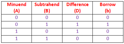
Hence, from truth table it is found that,
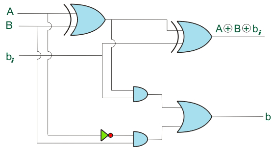
The above equations can be represented using logic gates.
The above circuit is logical half substractor circuit.
Full Substractor
It’s impractical to limit subtraction to single-bit binary numbers, as binary numbers typically involve multiple bits. Subtraction is executed bit by bit from the least significant bit (right) to the most significant bit (left). Each bit of the minuend and subtrahend is subtracted, potentially incorporating a borrow bit from the previous bit. This process, handled by a combinational logic circuit known as a full subtractor, continues to the most significant bit. Unlike a half subtractor, the full subtractor processes three inputs per bit.
Two inputs are for the minuend and subtrahend bits and third input is for borrowed which comes from previous bits substraction. The outputs of full adder are similar to that of half adder, these are difference (D) and borrow (b).
The combination of minuend bit (A), subtrahend bit (B) and input borrow (bi) and their respective differences (D) and output borrows (b) are represented in a truth table, as follow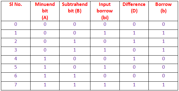
Let us draw K-map for D and b.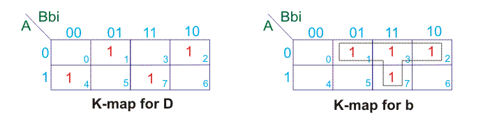
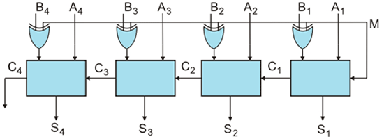
Binary Adder Substractor
We have developed circuits for both a 4-bit binary parallel adder and a 4-bit binary subtractor. These circuits are similar, with the main difference in the subtractor being that the subtrahend bits are inverted and the least significant bit (LSB) receives an input borrow bit set to 1.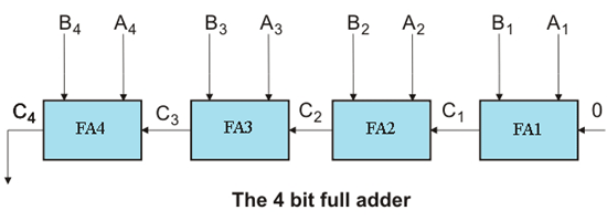
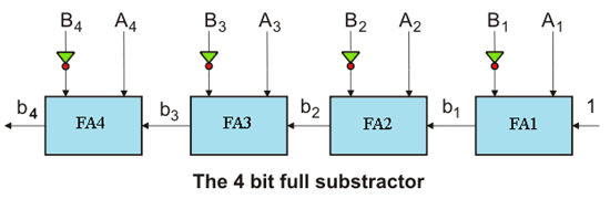
In the above 4 bit full adder circuit, third input to LSB Adder (FAI) is 1. In addition to that, in full substractor substandent bits, i.e. B1, B2, B3 and B4 are inverted.
We can combine these two circuits (Adder and Substractor) in one circuit by controlling B1, B2, B3 and B4 terminals and third input of LSB adder unit (FAI). We know that,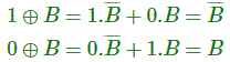
So, we can use XOR gate at each input B1, B2, B3 and B4 with control input M (either 1 or 0).
Now, if M = 1, B1, B2, B3 and B4 will be complemented. At the same time if third input of FAI is 1, the circuit becomes substractor. So, M = 1 is also to be fed to the third input of FAI in substractor.