

- Polarity Test Definition: A polarity test of transformer is a method to ensure correct polarity alignment when connecting transformers in parallel.
- Dot Convention: The dot convention identifies the polarity of windings in a transformer, showing how voltage is induced.
- Additive Polarity: In additive polarity, the voltage between primary and secondary windings adds up, used in small transformers.
- Subtractive Polarity: In subtractive polarity, the voltage between primary and secondary windings is the difference, used in large transformers.
- Testing Procedure: The polarity test involves using voltmeters to check if the voltages add or subtract correctly, ensuring proper connection.
Current flows from a high voltage point to a low voltage point because of the potential difference. Electrical polarity describes the direction of this current flow. In a DC system, one pole is always positive, and the other is negative, so the current flows in one direction. In an AC system, the terminals change polarity periodically, changing the direction of the current.
We use dot convention to identify the voltage polarity of the mutual inductance of two windings. The two used conventions are:
- If a current enters the dotted terminal of one winding, then the voltage induced on the other winding will be positive at the dotted terminal of the second winding.
- If a current leaves the dotted terminal of one winding, then the polarity of the voltage induced in the other winding will be negative at the dotted terminal of the second winding.
Distribution transformers need to operate continuously and handle high demand during peak times. To manage this, we connect transformers in parallel.
Paralleling is done by connecting same polarity terminals of the primary winding together. A similar procedure is done for the secondary winding. Paralleling will increase the power supplying capacity and also the reliability of the system.
We perform a polarity test on parallel transformers to ensure we connect the same polarity windings, not the opposite. Connecting opposite polarities can cause a short-circuit and damage the transformer.
We can categorise the polarity of the transformer to two types,
- Additive Polarity
- Subtractive Polarity
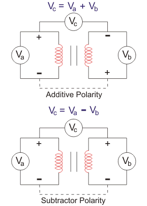
Additive Polarity
In additive polarity, the voltage (Vc) between the primary side (Va) and the secondary side (Vb) will be the sum of both high voltage and the low voltage, i.e. we will get Vc = Va + Vb
Subtractive Polarity
In subtractive polarity, the voltage (Vc) between the primary side (Va) and the secondary side (Vb) will be the difference of both high voltage and the low voltage, i.e. we will get Vc = Va – Vb
In subtractive polarity, if Vc = Va – Vb, it is a step-down transformer and if Vc = Vb – Va, it is a step-up transformer.
We use additive polarity for small-scale distribution transformers and subtractive polarity for large-scale transformers.
Procedure of Polarity Test of Transformer

- Connect the circuit as shown above with a voltmeter (Va) across primary winding and another voltmeter (Vb) across the secondary winding.
- If available, take down the ratings of the transformer and the turn ratio.
- We connect a voltmeter (Vc) between primary and secondary windings.
- We apply some voltage to the primary side.
- By checking the value in the voltmeter (Vc), we can find whether it is additive or subtractive polarity.
If additive polarity – Vc should be showing the sum of Va and Vb.
If subtractive polarity – Vc should be showing the difference between Va and Vb.
Caution: Be careful that the max. measuring the voltage of voltmeter Vc should be greater than the sum of Va (Primary winding) and Vb (Secondary winding) otherwise during the additive polarity, the sum of Va and Vb comes across it.
Note: If additive polarity is needed but we have subtractive, we can fix it by keeping one winding as is and reversing the other winding’s connections. The same applies if we need subtractive polarity but have additive.
I find the explanation very easy to understand.