

- Schrage Motor Definition: A Schrage motor is defined as a combination of a wound rotor induction motor and a frequency converter with primary, secondary, and tertiary windings.
- Operation Principle: The Schrage motor operates by creating a rotating field through three-phase currents in the primary winding, causing the rotor to move in the opposite direction of the synchronous field.
- Speed Control: Speed control is achieved by adjusting the brush displacement, which changes the phase of the injected emf relative to the slip emf.
- Power Factor Control: Power factor improvement is achieved by introducing an angular displacement between the tertiary and secondary winding axes, aligning the emf phasors correctly.
- Characteristics of Schrage Motor: The Schrage motor’s slip and speed at no load depend on machine constants and brush separation, allowing for two different speeds based on the phase of the injected emf.
A Schrage motor is essentially a combination of a wound rotor induction motor and a frequency converter. Unlike a standard induction motor, the primary winding of a Schrage motor is on the rotor, and the secondary winding is on the stator. There is also a tertiary winding connected to the commutator. The primary and tertiary windings are housed in the same rotor slots and are mutually coupled. The secondary winding terminals connect to the commutator through three sets of movable brushes (A1A2, B1B2 and C1C2). The brush positions can be adjusted with a wheel at the back of the motor, controlling the injected emf for speed and power factor regulation.
Operation Principle of Schrage Motor
At standstill, three-phase currents in the primary winding produce a rotating field. This rotating field cuts the secondary winding at synchronous speed (ns).
Therefore according to Lenz’s law the rotor will rotate in a direction so as to oppose the cause i.e. to induce slip frequency emfs into secondary. Therefore the rotor rotates opposite to the direction of rotation of synchronously rotating field. Now air gap field is rotating at slip speed ns – nr with respect to secondary. Therefore the emf collected by the stationary brushes is at slip frequency and hence suitable for injection into secondary.
Speed Control of Schrage Motor
Speed control of schrage motor is possible by varying the injected emf into the motor which can be controlled by changing the angular displacement between the two brushes. To understand the speed control of schrage motor let us understand the speed control in WRIMs using injected emf method.
Consider the following rotor circuits (values are only for illustration purpose).
Let initially electrical torque (Te) = load torque (Tl) = 2Nm
Rotor current Ir = 2A.
Let sE2 = slip emf induced in the rotor ckt.
And Ej = emf injected in the rotor ckt.
Case 1: When Ej is in phase opposition to sE2
Now the rotor current becomes Ir = 1A. Therefore Te < Tl due to which motor decelerates. Therefore ωr decreases. That implies slip increases. Therefore ωr decreases till sE2 becomes 15V and Ir = 2A i.e till Te = Tl again.
Case 2: When Ej is in phase with sE2
Now the rotor current becomes 3A. Therefore Te > Tl due to which motor accelerates. Therefore ωr increases. That implies slip decreases. Therefore ωr increases till sE2 becomes 5V and Ir = 2A i.e till Te = Tl again.
From the above analysis it can be seen that to increase speed the injected emf should be in phase with slip emf in the rotor. To decrease speed the injected emf should be out of phase with the slip emf in the rotor.
Now based on the above principles we shall take a look at the speed control of schrage motor.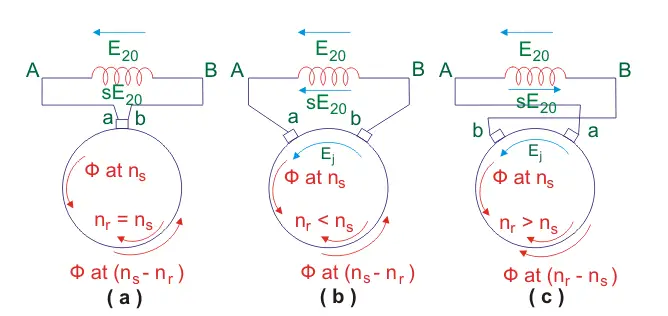
In the above figure
E20 = standstill emf induced in the secondary.
sE20 = induced emf at any slip s.
a, b = brush terminals.
In fig (a) both the brushes are connected to the same commutator segment and hence are short circuited. The injected emf in this case is zero. Therefore rotor rotates with speed close to synchronous speed.
In fig(b) the brushes a and b are separated by an angular displacement θ such that the tertiary winding axis between brushes a and b is coincident with secondary winding axis. Now on tracing the path BAabB we find that injected emf Ej is in phase opposition to E20. Therefore from above discussed principles speed of the motor shall decrease from what it was in case a. Hence the motor operates at sub synchronous speeds i.e. nr < ns.
In fig(c), the brush positions are interchanged. Tracing the path BAabB shows that the injected emf is in phase with the standstill emf (E20). Therefore, the motor speed increases from what it was in case (a), operating at a super-synchronous speed (nr > ns).
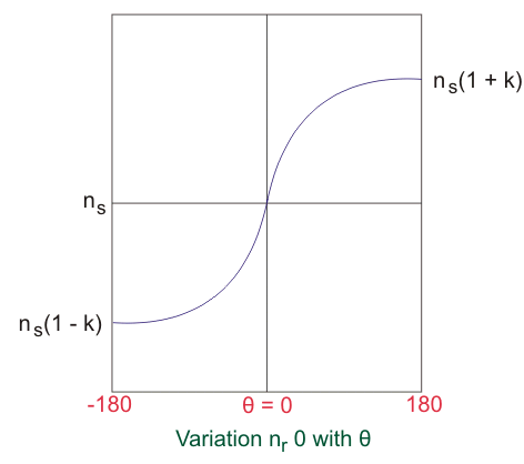
For any brush separation θ the injected emf is given by
From the equation it can be seen that minimum value of injected emf Ej = 0 at θ = 0 (i.e. when the brushes are short circuited). And maximum value of injected emf is Ej = Ejmax at θ = 90 degrees (i.e. when the brushes are one pole pitch apart).
Power Factor Control
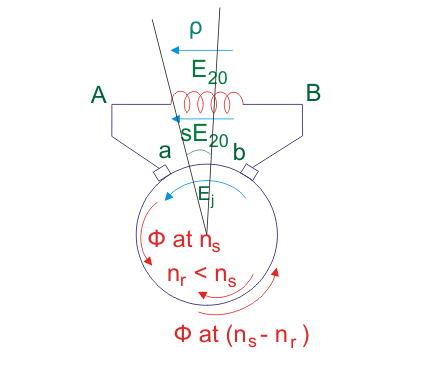
To improve the power factor, an angular displacement (ρ) is introduced between the tertiary and secondary winding axes. The flux (φ) cuts the tertiary winding axis after an angular displacement of ρ degrees, causing the emf phasor (–Ej) to lag by an angle ρ.
The phasor diagram for the two cases is as shown below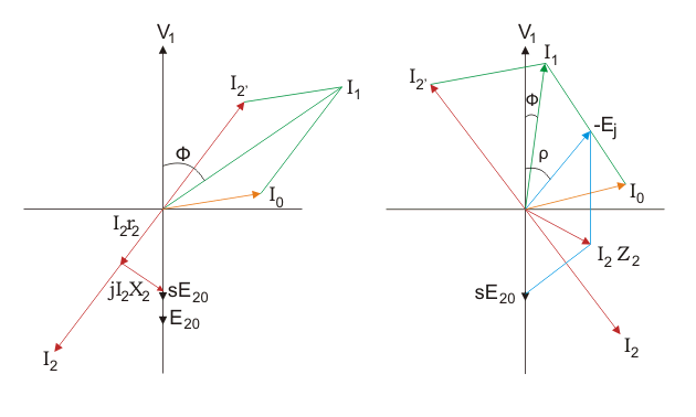
The phasor diagram has been constructed based on the following equations:
I2 lags I2Z2 by some angle θ. I2’ is draw opposite to I2. The resultant of I2’ and magnetizing current I0 gives the primary current I1.
From the phasor diagram it is clear that if the tertiary winding axis and secondary winding axis are displaced by an angle ρ then power factor improves.
Characteristics of Schrage Motor
If we apply KVL to secondary circuit then we get
Under no load conditions I2 value is very small and hence the can be neglected.
Therefore we have,
Where, s0 is the no load slip
Where,
Ejmax is the transformer emf induced in the Tertiary winding.
φm = max flux linkage
fs = supply frequency
Z = number of conductors in tertiary
A = number of parallel paths
Also
Where,
E20 = the transformer emf induced in the secondary.
N2’ = effective number of turns in the secondary
Now on substituting these values in the expression of no load slip we get
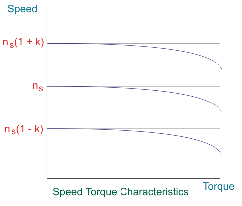
This implies values of slip depend completely on machine constants and the brush separation.
This shows that two different speeds are possible at no load depending on the phase of injected emf. The magnitude of these speeds can be controlled by adjusting the brush separation.
Under load conditions
Applications
Used in drives requiring variable speed such as cranes, fan, centrifugal pumps, conveyors etc.