

- Negative Feedback Definition: Negative feedback in an op amp is defined as connecting the output to the inverting input through a resistor to control the gain.
- Closed Loop Gain Definition: Closed loop gain is the gain of an op amp with negative feedback, determined by the feedback resistance divided by the input resistance.
- Operational Amplifier Gain: The gain of an op amp without feedback is very high, but practical gain is controlled using negative feedback.
- Example Calculation: For a 741 op amp with 10 kΩ input resistance and 20 kΩ feedback resistance, the closed loop gain is 2.
- Setting Desired Gain: By choosing the right resistances for feedback and input, you can set the op amp’s gain to your desired value.
Negative Feedback in Op Amp
We obtain Negative feedback in an op amp by connecting output terminal of an op amp to its inverting input terminal through a suitable resistance as shown below.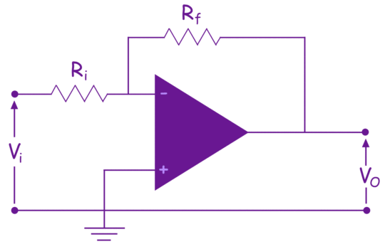 The gain of an op amp with negative feedback is called closed loop gain.
Closed Loop Gain of Op Amp
When we connect a feedback resistor and a resistance in series with the inverting input terminal of an op amp, the system’s gain becomes the negative ratio of the feedback resistance to the input resistance. The op amp has its own very large gain, ideally infinite. By choosing the appropriate values of series input resistance (Ri) and feedback resistance (Rf), we can set the system’s gain regardless of the op amp’s own gain (open loop gain).

To understand the closed loop gain of a 741 op amp, let’s look at an example. The 741 operational amplifier has the following parameters:
| Parameter | Value |
| Open Loop Gain | 2 × 10⁵ |
| Input Resistance | 2 MΩ |
| Output Resistance | 5 Ω |
Let us find the closed loop gain of the op amp when we connect a 10 kΩ resistance in series with the inverting terminal and a 20kΩ resistance as feedback path.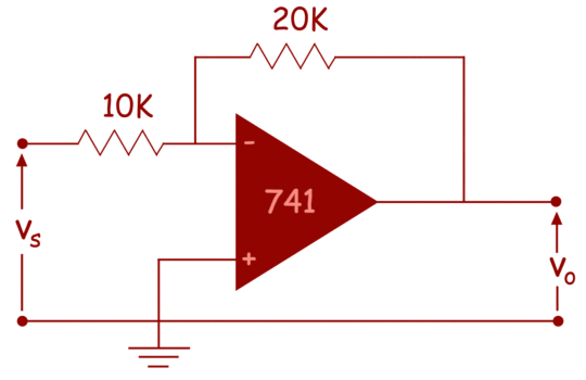
The equivalent circuit of the op amp with the input source is shown below: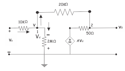
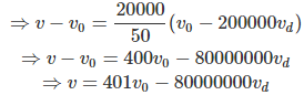
Let us assume, the voltage at node 1 is v. Now applying Kirchhoff current law at this node. we get,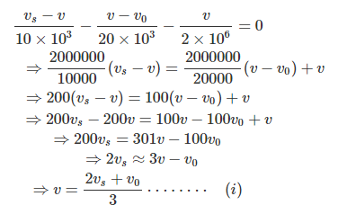
Now by applying Kirchhoff current law at node 2 get,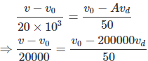
Now, from the figure it is found that,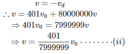
From equation (i) and (ii) we get,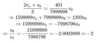
So, the open loop gain of the op amp is, 2 × 10⁵.
whereas closed loop gain comes to only 2.
Let us take another example of closed loop gain of an op amp.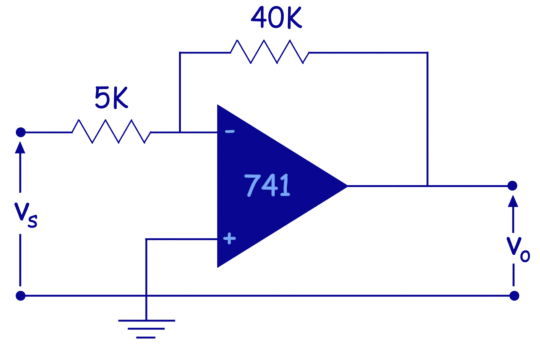
The equivalent circuit of above 741 op amp circuit can be redrawn as,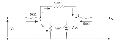
Now, consider voltage at node 1 is v applying Kirchhoffs current law at node 1. We get,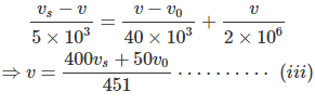
Now, applying Kirchhoffs current law at node of the equivalent circuit, We get,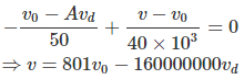
Now,
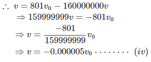
From the equation (iii) and (iv), we get,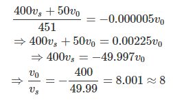
So, the closed loop gain of the above op amp circuit is 8.
So, it is clear that by choosing a suitable resistor for feedback in an op amp circuit, we can set the desired gain.