- Master Slave Flip Flop Definition: A master slave flip flop is defined as a combination of two flip-flops where the first is the master and the second is the slave.
- Triggering Mechanism: The master flip-flop is triggered by an external clock pulse, while the slave flip-flop is triggered by the inverted clock pulse.
- Pulse-Triggered Operation: The master slave flip flop, also known as a pulse-triggered flip-flop, completes its operation after one full clock pulse.
- Truth Table of Master Slave Flip Flop: The master slave flip flop truth table illustrates the timing of the master and slave outputs, with the slave output being delayed by half a clock cycle.
- Structure: The flip-flop consists of NAND gates and an inverter, with a master part and a slave part.
A master slave flip flop is a combination of two flip-flops: the first is the master, and the second is the slave (Figure 1). The master flip-flop is triggered by an external clock pulse, while the slave is triggered by the inverted clock pulse. This means data enters the flip-flop at one edge of the clock pulse and exits at the other edge. A master slave flip flop completes its operation after one full clock pulse, so it is also known as a pulse-triggered flip-flop.

The internal structure of a master-slave JK flip-flop, using NAND gates and an inverter to complement the clock signal, is shown in Figure 2. NAND gate 1 (N1) has three inputs: the external clock pulse (Clock), input J, and output Q̅. NAND gate 2 (N2) also has three inputs: the external clock pulse (Clock), input K, and output Q.
The outputs of N1 and N2 are connected to the inputs of criss-cross connected gates N3 and N4. Together, these four gates (N1, N2, N3 and N4) form the master part of the flip-flop. The slave part is formed by a similar arrangement of four gates: N5, N6, N7 and N8.
From figure it is also evident that the slave is driven by the outputs of the master (M1 and M2), which is in accordance with its name master-slave flip-flop. Further the master is active during the positive edge of the clock due to which M1 and M2 change their states; depending on the values of J and K. However at this instant the outputs of the overall system (master-slave JK flip-flop) remains unchanged as the slave will be inactive due to positive-edge of the clock pulse. Similar to this, the slave decides on its outputs Q and Q̅ depending on its inputs M1 and M2, during the negative edge of the clock during which the master will be inactive.
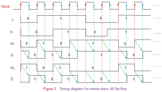
The truth table corresponding to the working of the flip-flop shown in Figure 2 is given by Table I. Here it is seen that the outputs at the master-part of the flip-flop (data enclosed in red boxes) appear during the positive-edge of the clock (red arrow). However at this instant the slave-outputs remain latched or unchanged. The same data is transferred to the output pins of the master-slave flip-flop (data enclosed in blue boxes) by the slave during the negative edge of the clock pulse (blue arrow). The same principle is further emphasized in the timing diagram of master-slave flip-flop shown by Figure 3. Here the green arrows are used to indicate that the slave-output is nothing but the master-output delayed by half-a-clock cycle.
Moreover it is to be noted that the working of any other type of master-slave flip-flop is analogous to that of the master slave JK flip-flop explained here.