

- Dynamic Shift Register Definition: A dynamic shift register is defined as a type of shift register that uses dynamic inverters and temporary charge storage techniques, requiring frequent refresh cycles to maintain data.
- Working Principle: The working principle involves shifting data from input to output through the controlled charging and discharging of capacitors using clock signals.
- Clock Signals: Non-overlapping, complementary clock signals control the operation of the shift register, managing the timing of data shifts.
- Data Storage and Leakage: Data is stored as charge on capacitors, which can leak, necessitating periodic refreshing to maintain accurate logic levels.
- Advantages and Design Variations: Dynamic shift registers are simpler to fabricate, have high package density, and can be designed using various approaches, though their power consumption increases with frequency.
Shift registers can be classified into two types viz., Static Shift Registers and Dynamic Shift Registers. Static shift registers are composed of flip-flops and are capable of storing the information within them for indefinite period of time. On the other hand, dynamic shift registers comprise of dynamic inverters and employ temporary charge storage techniques and hence require frequent refresh cycles to store the data.
Figure 1 shows a dynamic shift register formed by a combination of NMOS transmission gates (red circled components, G1 and G2) and NMOS depletion-mode inverters (blue circled components, {D1, N1} and {D2, N2}). Here ϕ1 and ϕ2 are non-overlapping, mutually complementary clock signals, while C1 and C2 represent the gate-to-source capacitances of Stage 1 and Stage 2, respectively. Further these capacitances are considered to be depleted of charge in their initial state.
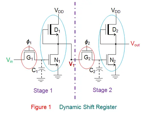
Now consider Vin = 0V and ϕ1 = VDD, which correspond to the logic states 0 and 1 respectively. For this case, the gate G1 will be open (non-conducting) and thus the capacitor C1 will remain in its uncharged state.
This causes the output voltage level of the inverter circuit in Stage 1 (formed by D1 and N1) to go high i.e. V1 = VDD (assuming zero threshold voltage for all the devices in the circuit – just for simplicity). However for this, ϕ1 is to be maintained in its high state for sufficient amount of time, as the charging of the capacitor is a gradual process (considering RC time constant issue).
When ϕ2 goes high, gate G2 closes, allowing capacitor C2 to gradually charge to VDD (= V1), which limits the clock frequency. As the voltage across capacitor C2 rises, the output voltage at Stage 2 decreases due to the inverting action of the circuit formed by D2 and N2, causing Vout to go low (= 0V). Thus, the state of Vin shifts to Vout.
Similarly, if Vin = VDD while ϕ1 = VDD, C1 charges to VDD through G1, causing the output voltage of Stage 1, V1, to go low. If ϕ2 = VDD, gate G2 closes, and capacitor C2 discharges while Vout gradually increases. Thus, Vout = VDD, reflecting the logic high state of Vin. This shows that Vin shifts to Vout under clock control. The circuit in Figure 1 acts as a single-stage shift register. An n-stage dynamic shift register can be made by cascading n stages.
The working of the single stage dynamic shift register can be further emphasized by the timing diagram shown by Figure 2.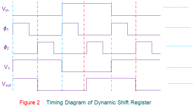
Dynamic shift registers store information as charge on the gate-to-substrate parasitic capacitance of electronic (especially MOS) devices. However, this charge can leak, so periodic data refreshing is needed to keep logic levels accurate. This is done by continuously shifting data from one stage to another and feeding the last stage’s output back to the first stage. Therefore, dynamic shift registers must operate at a minimum clock frequency.
Dynamic shift registers are simpler in terms of fabrication and have high package density due to their smaller size. However it is to be noted that their advantage of less power consumption is cursed by the fact that the power consumed increases with the increase in frequency. Further there are many design variations available in case of dynamic shift registers like dynamic shift registers using enhancement load, dynamic shift registers using CMOS devices and so on including Ratioed Logic approach as well as Ratio less Logic approach. Nevertheless, the basic working principle remains the same.