

- Dipole Antenna Defined: A dipole antenna is a type of RF antenna consisting of two identical conductive elements, operating effectively at half the wavelength of its frequency.
- Basic Design: The antenna’s simple structure—two rods connected in the middle—makes it a fundamental model for many other types of antennas.
- Radiation Patter: Dipole antennas typically emit signals in a pattern that is strongest perpendicular to the antenna, ideal for broad area coverage.
- Variations: Different types of dipole antennas, such as the folded dipole and the fan dipole, are designed for specific uses, enhancing signal strength and impedance.
- Applications: Widely used in telecommunications, dipole antennas serve crucial roles in transmitting and receiving radio frequencies in numerous devices.
What is a Dipole Antenna?
A dipole antenna, also called a doublet or dipole aerial, consists of two conductive elements like rods or wires. This antenna type emits a radiation pattern similar to an elementary electric dipole, making it both simple and widely used.
The metal wires of a dipole antenna are each half the maximum wavelength (i.e., ) in free space at the operating frequency.
This wire or rod is split at the center, and the two sections are separated by an insulator, these sections are known as an antenna section.
These two sections of the antenna connect to a feeder, like a coaxial cable, at the center. The wavelength, defining the distance between consecutive peaks or troughs, influences where the feed point is placed.

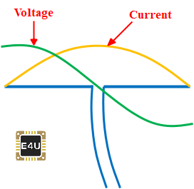
The radio-frequency (RF) voltage source is applied to the center between the two sections of the dipole antenna. This voltage and a current flowing through the two conductive elements produce a radio signal or an electromagnetic wave to be radiated outwards from the antenna.
The current is maximum and voltage is minimum at the center of the dipole antenna. Conversely, the current is minimum and voltage is maximum at the ends of the dipole antenna.
The radiation pattern of the basic dipole antenna is shown in the figure below. It is perpendicular to the axis of the antenna.
Note that the radiation pattern is the graphical representation of the radiation properties of the antennas as a function of space i.e., the radiation pattern of the antenna describes how the antenna radiates energy out into space.

The dipole antenna is one type of transducer which converts electrical signals into RF electromagnetic waves and radiates them at the transmitting side and converts RF electromagnetic waves into electrical signals at the receiving side.
Dipole Antenna Design
Dipole antennas can be designed to operate across various bands—HF (high frequency), VHF (very high frequency), and UHF (ultra-high frequency)—of the radio frequency spectrum.
Let’s design a 1 MHZ dipole antenna.
Selection of Length of the Dipole Antenna
As we know that the wavelength of a radio wave or any other wave varies inversely proportional to the frequency. it is given by:

(1) 
Where, C = velocity of light = 
f = frequency, in Hertz
 = wavelength, in meter
Thus,

(2) 
Now, at a half-wavelength, the length of the antenna is given by,

(3) 
Thus, from equation (3) we can say that, if we used a 1 MHz radio transmitter, then the basic length of the antenna wire will be 150 meters or 492 feet or 5905 Inches.
This is correct if we neglect the “end effect”. This “end effect” is the dielectric effect of the air at the end of the antenna that increases the effective length of the antenna. Due to the end effect, an antenna wire acts as 5% longer than the actual length. This will produce interference between the exciting and oscillating currents and due to that oscillation amplitude may be weakened.
Hence, to counterbalance the “end effect” and to make the antenna works properly, it is necessary to cut the antenna wire about to 5% and makes its physical length approximately 95% of half of the wavelength.
Thus, to get the practical  length of the antenna wire, the value multiplied by a factor K to the basic length of the antenna wire, i.e.,

(4) 
The value of K depends on the thickness of the conductor and the operating frequency. This value of K is accurate for antenna wire at a frequency of up to 30 MHz.
Selection of the Feed Impedance or Radiation Resistance
The feed impedance of a dipole is defined by the ratio of the voltage and the current at the feed point. It is typically fed at the voltage minimum and current maximum point.
To ensure the maximum transfer of energy from the feeder, or source/load, the feed impedance of the dipole antenna should be the same as that of the source or load. By matching the feed impedance to the source or load impedance, the antenna can operate to its maximum efficiency.
The radiation resistance or an input feed impedance of an ideal dipole antenna in free space can be approximately modelled by a 73 Ω impedance and under practical conditions it varies from 60 Ω to 70 Ω. The antenna impedance can be changed by varying the length or shape of the wires.
Many types of coaxial cable have a characteristics impedance of 75 Ω hence, the dipole antenna can be fed with coaxial cable of 75 Ω two wire which is a good match for a half-wave dipole antenna.
Also, the half-wave dipole can be fed with a transmission line of impedances 300 Ω, and 600 Ω open wire line with folded dipoles according to the power handling capabilities.
Use Balanced Feeder or Balun
The dipole antenna is the balanced antenna. Hence, it is necessary to use a balanced feeder. A balanced feeder consists of two parallel conductors. The currents flowing in both the conductors are equal in magnitude but opposite directions. Hence, the radiating field from them cancels out and no power dissipated. The spacing between the conductors has normally kept about 0.01 wavelengths. If a coaxial feeder needs to be used, then the balanced balun must be used.
Coaxial Cable
The most common feeder that is used to feed the antenna is coaxial cable or coax cable. It is often referred to as RF cable.
A coaxial cable carries current in both the conductors. These currents are equal in magnitude but opposite directions. Due to that, all the radiating fields are linked within the cable and hence they are canceling out each other.
Thus, there is no radiating field outside the cable hence it is not affected by nearby any objects. Therefore, it is best suitable as a feeder to the dipole antenna.
Strain Insulator
A strain insulator is an electrical insulator that is designed to withstand the pull of a suspended electrical cable or wire.
It is inserted between two lengths of the conducting wire, to isolate them electrically from each other. It is used in overhead electrical wire, to support radio antennas and overhead power lines.
The overall design of a 1 MHz dipole antenna is illustrated in the figure below.

Types of Dipole Antennas
The most common types of a dipole antenna are the half-wave dipole antenna. There are many types of dipole antennas can be designed. Let’s explain the major types of dipole antennas in detail.
Folded Dipole Antenna
A folded dipole antenna is an array of the two-dipole antenna. If two dipole antennas are connected in parallel to forms a thin wire loop, then it is called a folded dipole antenna.
As the name implies that the form of the dipole antenna is folded back on itself. In the folded dipole antenna, two half-wave dipoles – one continuous and the other split at the center are folded and joined together in parallel at the ends. The split dipole is fed at the center by a balanced transmission line. Hence, the two dipoles have the same voltages at their ends and two identical currents are generated.
The radiation pattern of a folded dipole is the same as to an ordinary dipole but the input impedance of the folded dipole is higher and the directivity of a folded dipole is bi-directional.
Two-Wire Folded Dipole Antenna
If two dipole antennas are connected in parallel to form a thin wire loop, then it is known as a two-wire folded dipole antenna.
If the radius of both the conductors is equal, then equal currents flow in both the conductors in the same direction i.e., currents are equal in magnitude and phase. If the total current fed at the terminal is ‘I’ then each dipole will have current ‘I/2’. Thus, with the same power applied, only half of the current flows in the first dipole, and hence the input impedance increases and it becomes four times. The folded dipole antenna is shown in the figure below.

The general formula for impedance calculation for a folded dipole is given by,

Where, n = no. of antenna wire
Thus, for a two-wire folded dipole with equal radius, the input impedance or radiation resistance is given by

Therefore, the two-wire folded dipole can be fed with a conventional 300 Ω open-wire transmission line without any matching device.
Three Wire Folded Dipole Antenna (Folded Tripole)
If three dipole antennas are connected in parallel to form a thin wire loop, then it is known as a three-wire folded dipole antenna or Folded Tripole antenna.
If three wire folded dipole antennas are used with equal radii, then the equal current flows in all the three conductors. If the total current fed at the terminal is ‘I’ then each dipole will have current ‘I/3’.
Thus, with the same power applied, only one-third of the total radiating current flows in the first dipole, and hence the input impedance increases and it becomes nine times. The folded dipole antenna is shown in the figure below.

Thus, for a three-wire folded dipole with equal radius, the input impedance or radiation resistance is given by

Therefore, three-wire folded dipole or folded tripole can be fed with a conventional 600 Ω two-wire open transmission line without any matching device.
So, the folded dipole antenna or tripole antenna has an important impedance transforming properties. This makes it easy to match with a transmission line that feeds the antenna. It is also possible to change the input impedance by keeping the radius of the two dipoles unequal. In this condition, a larger current flow through a thicker dipole and hence we can maintain any desired input impedance.
Advantages of a Folded Dipole Antenna
Some of the advantages of a folded dipole antenna include:
- It has high input impedance; hence it makes it easy to match with the transmission line.
- It has wideband frequency i.e., wide bandwidth, hence it is suitable for FM and TV broadcast.
- It has high gain and high directivity compared to a simple dipole antenna hence, it can be used in the Yagi-Uda antenna.
FM Dipole Antenna
FM dipole antenna is defined as the vertically polarized half-wave half dipole antenna. The FM dipole antenna is mostly used as it is to build and it is suitable to provide improved reception of VHF FM broadcast. The FM dipole antenna is shown in the figure below.

The radiation pattern of the FM dipole antenna is perpendicular to the axis of the antenna i.e., It is horizontal because the FM dipole antenna is a vertically polarized half-wave dipole antenna. The radiation pattern of the FM dipole antenna is shown in the below figure.

The FM dipole antenna is generally used for FM broadcasting frequency range between 88 MHz to 108 MHZ.
Fan Dipole Antenna
Fan dipole or Multi-band wire antenna is one in which multiple dipoles are connected with a common feed line, and they are spread out like a fan hence it is called a fan dipole antenna.
As the name implies that the form of the fan dipole antenna looks like a fan. It is also known as a Parallel dipole antenna.
In the fan dipole antenna, each dipole of the multi-band is cut from the center of the bands and connected to a common feeder. The dipole should be cut from where we want it to radiate. When the signal is transmitted, we only receive the signal from that band which is radiating, because the other dipoles have a higher impedance compared to that radiating element.

The fan dipole antenna is shown in the above figure. It is 4 Bands fan dipole antenna. Here, we used 80 m, 40 m, 20 m, and 10 m multi-band dipole that are connected in parallel with a common feeder line.
When 80 m dipole is radiating means the current pass through 80 m dipoles, in this condition, we receive signal only from 80 m bands because it has a lower impedance while other 40 m, 20 m, and 10 m band have a higher impedance compared to the 80 m radiating element.
Similarly, when the 40 m dipole is radiating, we only receive the signal from the 40 m bands because it has a lower impedance compared to the other dipole. Note that according to Kirchhoff’s Current Law, other dipoles are also radiating but not efficiently.
Half-Wave Dipole Antenna
The Half-Wave Dipole Antenna is the most widely used type of dipole antenna. As the name suggests that, the total length of the dipole antenna is equal to the half-wavelength () at the frequency of operation.
It is known as a half-wavelength dipole or simply dipole or doublet. It is also known as the Hertz antenna.
The half-wave dipole antenna consists of a two-quarter wavelength conductor with the feed point at the center. It is the symmetrical antenna in which the two ends are at the equal potential to the center point.
The current distribution in the half-wave dipole antenna is approximately sinusoidal along the length of the dipole i.e., a standing wave in nature. The basic half-wave dipole antenna and voltage and current distribution on it are shown in the below figure.

The radiation pattern of the half-wave dipole antenna is shown in the below figure. It shows that the directions of maximum radiation are perpendicular to the conductor or the axis of the antenna. It is also perpendicular to the direction of the antenna current.

The half-wave dipole antenna can operate around 3 kHz to 300 GHz frequency range; hence It is mostly used in radio receivers.
Short Dipole Antenna
The short dipole antenna is the simplest type of antenna from all the antennas. A short dipole antenna is one in which the length of the wire is less than half of the wavelength i.e.,(
 ).
).
In a short dipole antenna, the feed impedance starts to increases and its response is less dependent upon the frequency changes. The current distribution in the short dipole antenna is approximately triangular.
The length of the short dipole antenna in between  to
to  . i.e.,
  . The current distribution on the short dipole antenna is approximately triangular. The basic short dipole antenna and current distribution on it are shown in the below figure.


The radiation pattern of the short dipole antenna is simply a circle. It is slightly different compared to the half-wave dipole antenna. The radiation pattern of the short dipole antenna and its comparison with the half-wave dipole antenna is shown in the below figure.


A short dipole antenna is used in place of the full half-wave dipole antenna in certain applications where the full half-wave dipole antenna is too large.
What is a Dipole Antenna Used for (Applications)?
Some of the applications of Dipole Antenna include:
- The dipole antenna is widely used in radio and telecommunications.
- An antenna can be used either as a transmitting antenna or a receiving antenna. A transmitting antenna is used to converts electrical signals into electromagnetic waves and radiates them. While a receiving antenna is used to converts electromagnetic waves into electrical signals. In two-way communication, the same dipole antenna can be used for both transmission and reception.
- A half-wave dipole antenna is used in radio and television receivers.
- A Folded dipole antenna is used in Yagi-Uda antennas for terrestrial television (TV) reception using the balanced line of Z0 = 300 Ω because a folded dipole antenna has a high input impedance and hence it is easily matching with the impedance of the transmission line.
- The Folded dipole antenna is used in wideband operations such as FM and TV (Television) broadcast.
- VHF and UHF antennas are used in land mobile communication in the Coastal areas, Public Safety, Public communication, and Industrial applications.
- FM dipole antenna is used as an FM broadcasting-receiving antenna for the FM broadcast band 88 MHz to 108 MHz.
- A parabolic reflector antenna is commonly used for satellite communications, radio astronomy, and for various types of radio communication links.