- DTL NAND Gate Definition: A DTL NAND gate is defined as a digital logic gate that uses diodes and transistors to produce a NAND logic function.
- Operation with 0V Inputs: When both inputs are 0V, the diodes are forward biased, keeping the transistor off and making the output high (1).
- Operation with Mixed Inputs: If either input is 0V, the output remains high due to the forward-biased condition of the diodes.
- Operation with 5V Inputs: When both inputs are 5V, the diodes turn off, the transistor switches on, and the output becomes low (0).
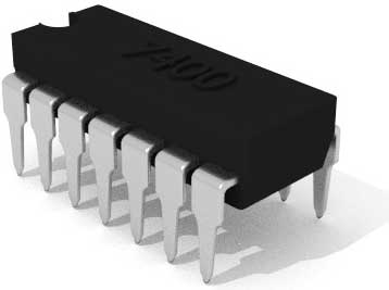
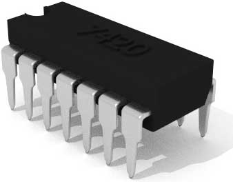
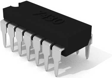
- NAND Gate ICs: IC7400, IC7420, and IC7430 are common NAND gate ICs, each with different input configurations for various digital logic applications.
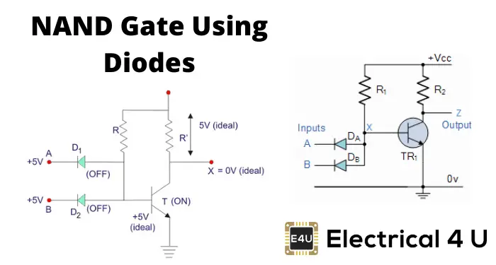
Realizing NAND Gate using Diode and Transistor
We will explain a two-input NAND gate circuit using diodes and transistors. This type of NAND gate is called a DTL NAND gate, which stands for Diode Transistor Logic NAND gate.
When both inputs A and B are at 0V, both diodes are forward biased (ON condition). The supply voltage finds a path to the ground through diodes D1 and D2, causing the full 5V to drop across resistor R. This prevents the base of transistor T from turning on, keeping it off. As a result, the output terminal X is high, or logical 1.
If either diode D1 and D2 is at 0V, the supply voltage still finds a path to the ground through the forward-biased diode. This keeps the output high or logical 1.

When both inputs are at +5V (logical 1), the diodes are off. This allows the supply voltage to reach the base of transistor T, turning it on and providing a path to ground. The entire 5V drops across resistor R’, making the output at terminal X 0V, or logical 0. Therefore, the output is 0 only when both inputs are +5V.
NAND Gate ICs
The IC7400 is a NAND gate IC with four two-input NAND gates. The IC7420 has two four-input NAND gates, and the IC7430 has one eight-input NAND gate.