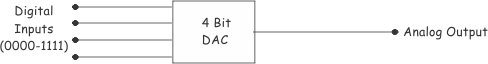
- DAC Definition: A Digital to Analog Converter (DAC) is defined as an electronic device that converts digital signals into equivalent analog signals.
- Working Principle: The working principle of a DAC involves using an op-amp and resistors to convert binary inputs into a proportional analog output.
- Binary Weighted Ladder: A binary weighted ladder is a common DAC circuit that uses resistors to sum digital inputs into an analog signal.
- Output Proportionality: The output of a DAC is linearly proportional to the decimal equivalent of the digital input.
- Voltage Levels: Each increment in the binary input increases the analog output by a fixed voltage amount, demonstrating the DAC’s precise conversion.
An op amp is extensively used as the main building block of a Digital to Analog Converter (DAC). A DAC is an electronic device in the form of an IC that converts digital signals to equivalent analog signals. DACs can be realized in many ways. One popular DAC circuit is the binary weighted ladder.
This DAC circuit functions as a summing amplifier designed with specific resistances.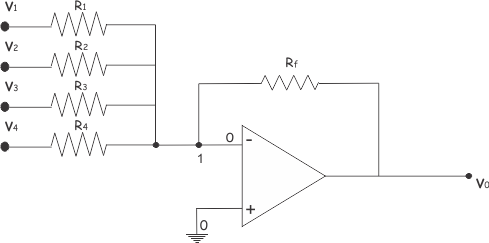
Applying Kirchhoff Current Law at node 1 of the circuit, we can analyze the current flow.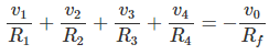
Before analyzing the DAC circuit, let’s assign values to the resistors connected in the circuit.
Such as, Rf = 10KΩ, R1 = 10KΩ, R2 = 20KΩ, R3 = 40KΩ and R4= 80KΩ.
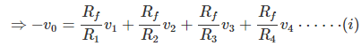
Putting these values in equation (i) we get,
Now, let us also apply voltage at input terminals either 0 or 1 volt. Putting , 0 volt at all inputs,(i.e. v1 = 0, v2 = 0, v3 = 0 and v4 = 0) we get,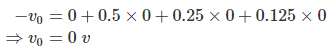
So, for digital input 0000, we get analog output 0 volt. Putting, 1V at last input only, (i.e. v1 = 0, v2 = 0, v3 = 0 and v4 = 1V), we get,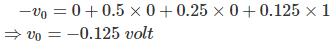
Similarly, for v1 = 0, v2 = 0, v3 = 1, v4 = 0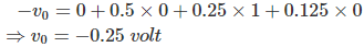
For, v1 = 0, v2 = 0, v3 = 1, v4 = 1
In this way the inputs and corresponding outputs can be represented in a table as shown below.
| Binary Input [v1 v2 v3 v4] | Decimal Value | Output(-v0) |
| 0000 | 0 | 0 |
| 0001 | 1 | 0.125 |
| 0010 | 2 | 0.25 |
| 0011 | 3 | 0.375 |
| 0100 | 4 | 0.5 |
| 0101 | 5 | 0.625 |
| 0110 | 6 | 0.75 |
| 0111 | 7 | 0.875 |
| 1000 | 8 | 1.0 |
| 1001 | 9 | 1.125 |
| 1010 | 10 | 1.25 |
| 1011 | 11 | 1.375 |
| 1100 | 12 | 1.5 |
| 1101 | 13 | 1.625 |
| 1110 | 14 | 1.75 |
| 1111 | 15 | 1.875 |
So, for each decimal number there is one unique output voltage level. From the table it is also seen that, form 0 to 15, for each increment there is an increase of output voltage level by 0.125 volt.
So, the output is analog and it is linearly proportional the decimal equivalent of digital inputs. The above example was of a four bit DAC. A four bit DAC can be represented as shown below.