
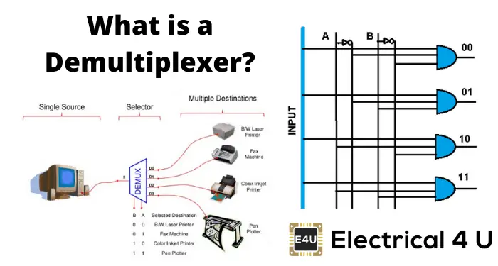
- Demultiplexer Definition: A demultiplexer (demux or data distributor) is defined as a circuit that distributes multiple outputs from a single input.
- Working Principle: It operates by using a control signal to select which output line will receive the input data.
- Types of Demultiplexers: Includes 1-to-2, 1-to-4, 1-to-8, and 1-to-16 types, based on the number of output lines.
- Communication Applications: Demultiplexers are crucial in communication systems for transmitting and receiving signals.
- ALU and Data Conversion: Used in ALUs for directing output to registers and in converters to change serial data to parallel data.
What is a Demultiplexer?
A demultiplexer (also known as a demux or data distributor) is defined as a circuit that can distribute or deliver multiple outputs from a single input. A demultiplexer can perform as a single input with many output switches. The demultiplexer’s output lines are ‘n’ in number, the select line number is ‘m’ and n = 2m. The control signal or select input code decides the output line to which the input has to be transmitted.
A demux can also work as a binary to decimal decoder. When the data input line is at logic 1, the binary input is given to the select input lines, which determine the output line. This makes the demux useful in designing multiple combinational circuits.
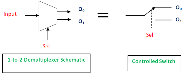
The function of a demultiplexer is essentially the reverse of a multiplexer. It takes one input and directs it to one of many outputs.
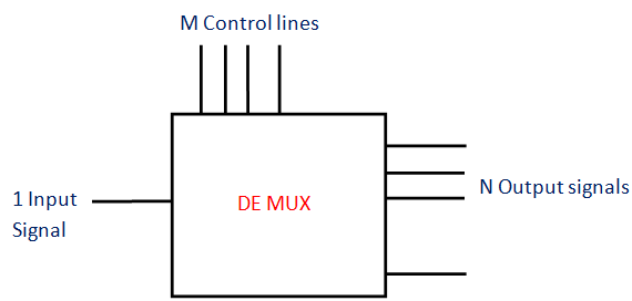
The pin diagram of the demultiplexer is in the figure below.
1 to 4 Demultiplexer
Here’s will analyze a 1 to 4 demultiplexer in a bit more detail.
Note that there are many other types of demultiplexers—e.g., 1-to-2, 1-to-8, 1-to-16 demultiplexer, etc. But for this article, we’ll focus on a 1 to 4 demultiplexer.
A 1 to 4 demultiplexer has:
- Input
1 input bit is present. Here it is Data D. - Outputs
The number of outputs is four. They are Y0, Y1, Y2, and Y3. - Control Bits
Two control bits are used here. They are A and B. The input data bit is sent to the data bit of the output lines depending on the select input or control bit’s value.
If the condition AB = 01, the second AND gate from the top are enabled (shown in the figure above).
At this moment, all the other three AND gates are in a disabled condition. So, input bit Data D is delivered to the output. Thus, Y1 = Data.
When the input is set as 0, Y1 will be low (i.e., 0), and when input is 1 (high), Y1 will be 1(high). Thus, we can say that the Y1 value will directly depend on input D. The other three outputs are 0 (low state).
If AB = 10, every other AND gate are disabled, excluding the second AND gate from the bottom.
So, input bit D is sent to Y2 output. Thus, Y2 = Data D.
Truth Table
| Data D | Control | Input | Outputs | |||
| – | A | B | Y0 | Y1 | Y2 | Y3 |
| 1 | 0 | 0 | 1 | 0 | 0 | 0 |
| 1 | 0 | 1 | 0 | 1 | 0 | 0 |
| 1 | 1 | 0 | 0 | 0 | 1 | 0 |
| 1 | 1 | 1 | 0 | 0 | 0 | 1 |
The examples of multiplexers are IC 74155 (4-to-1 multiplexer), IC 74154 (16-to-1 multiplexer, which has 4 control bits, 1 input bit, and the outputs are 16 bits)
Applications of Demultiplexer
Demultiplexers are used in several fields where there is a necessity of connecting a single source to several destinations. These applications of a demultiplexer include:
Communication System of Demultiplexer
Generally, the communication system includes transmission and reception of the signals. For these purposes, the multiplexer in the transmitting end and the receiving end’s demultiplexer have to work simultaneously.
Transmission uses a multiplexer to send signals. The single output from the multiplexer becomes the input to the demultiplexer. The demultiplexer then converts this input back to the original signals at the receiver end.
Arithmetic and Logic Unit (ALU) of Demultiplexer
With the implementation of the demultiplexer, the ALU’s output can keep in storage units or multiple registers. Here, the ALU output is given to the demultiplexer as its input.
The outputs of the demultiplexer are given to the multiple registers where the data is stored.
Serial to Parallel Converter of Demultiplexer
This converter can give (recreate) the parallel data from the received serial data. Here, the input serial data is set as the input of the demultiplexer.
This is done at regular intervals. At the control input of the demultiplexer, a counter is attached. The data signal is directed to the demultiplexer output with the help of this counter.
After every bit of data signal is stored, the demultiplexer output can be extracted. It can be read out in parallel.