

- Two Transistor Model of SCR Definition: The two transistor model of SCR is defined as a representation of an SCR using two interconnected transistors, one pnp and one npn, to explain its operation.
- SCR Structure: An SCR consists of four layers (pnpn) and can be split into two transistors, making its function easier to understand.
- Anode Current Analysis: The anode current in an SCR is analyzed by considering the currents and gains of the two transistors involved.
- Gate Current Impact: Applying a gate current (Ig) increases the cathode current (Ik), affecting the overall anode current.
- Positive Feedback Effect: The positive feedback effect in the two-transistor model causes a rapid increase in anode current, which can be moderated by external resistance.
The basic operating principle of an SCR can be understood using the two transistor model of SCR, which combines p and n layers.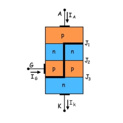
An SCR is a pnpn thyristor. By bisecting it, we see two transistors: one pnp transistor with J1 and J2 junctions and one npn transistor with J2 and J3 junctions.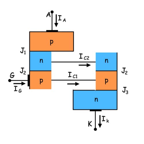
The relation between the collector current and emitter current is shown below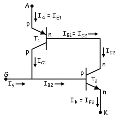
In this model, IC is the collector current, IE is the emitter current, ICBO is the forward leakage current, and α is the common base forward current gain.
Where, IB is base current and β is common emitter forward current gain.
Let’s for transistor T1 this relation holds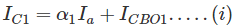
And that for transistor T2
By analyzing the two transistor model, we can determine the anode current.
From equation (i) and (ii), we get,
If applied gate current is Ig then cathode current will be the summation of anode current and gate current i.e.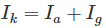
By substituting this valyue of Ik in (iii) we get,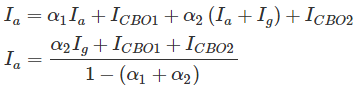
From this relation we can assure that with increasing the value of  towards unity, corresponding anode current will increase. Now the question is how increasing? Here is the explanation using two transistor model of SCR.
At the first stage when we apply a gate current Ig, it acts as base current of T2 transistor i.e. IB2 = Ig and emitter current of the T2 transistor IE2 = Ik. Hence establishment of the emitter current gives rise α2 as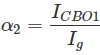
Presence of base current will generate collector current as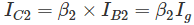
This IC2 is nothing but base current IB1 of transistor T1, which will cause the flow of collector current,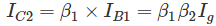
IC1 and IB1 lead to increase IC1 as 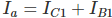 and hence, α1 increases. Now, new base current of T2 is
 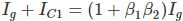 , which will lead to increase emitter current
 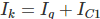 and as a result α2 also increases and this further increases
  .
.
As  , α1 again increases. This continuous positive feedback effect increases towards unity and anode current tends to flow at a very large value. The value current then can only be controlled by external resistance of the circuit.