

- 3 Phase Full Wave Rectifier Definition: A 3-phase full-wave diode rectifier combines two half-wave rectifiers to produce a lower ripple DC output.
- Circuit Diagram: Includes six diodes arranged to rectify the three-phase AC input into a smoother DC output.
- Diode Conduction: Each diode conducts for 120 degrees, and diode pairs conduct for 60 degrees.
- Output Ripple Frequency: The output voltage has a 300Hz ripple, which is six times the input AC frequency.
- Peak Inverse Voltage (PIV): The maximum reverse voltage a diode can withstand is √3 times the maximum phase voltage.
What is a Three Phase Full Wave Diode Rectifier?
A three-phase full-wave diode rectifier is obtained by using two half-wave rectifier circuits. The advantage of this circuit is that it produces a lower ripple output than a half-wave 3-phase rectifier. This is because it has a frequency of six times the input AC waveform.
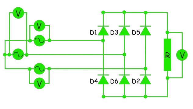
A three-phase full-wave diode rectifier with purely resistive load is shown below. The AC voltage supply is 110 V line to line and 50 Hz frequency.
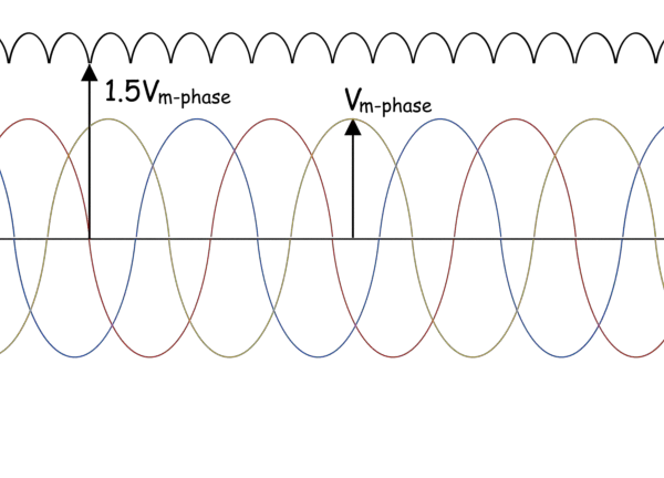
The voltage waveform across the load is shown in black in the figure. Vm-phase is the maximum phase voltage, and the minimum voltage across the load is 1.5 times Vm-phase.
In the circuit, diode D1 begins conducting at 30° when the R phase voltage is at its peak. Diode D1 stops at 150°, and diode D3 takes over when the Y phase voltage peaks.
Diode D1 conducts from 30° to 150° during the positive cycle, assisted by diode D6, which completes the return path to the three-phase source. Diode D6 handles the maximum negative voltage until 90°, when diode D2 takes over and completes the path with diode D1.
- Therefore each diode pair conducts for 60o, and each diode conducts for 120o.
- The load voltage has a ripple, and the frequency of this ripple is 6 × 50 = 300 Hz.
The magnitude of the DC voltage is the sum of the magnitude of the voltages in the two diodes that are conducting at any instant, which is incidentally also a particular line voltage depending on which diode pair is conducting.
The average of the output voltage across the resistive load is given by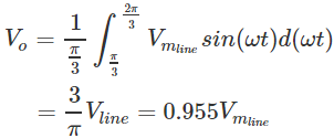
where,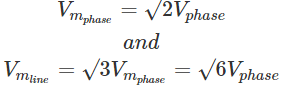
The RMS value of the output voltage is given by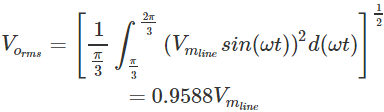
Ripple voltage,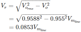
Voltage ripple factor,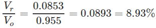
DC output power, 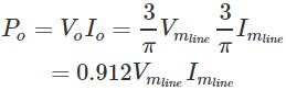
AC input power, 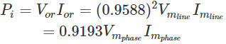
Efficiency,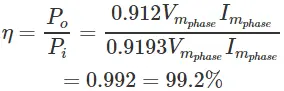
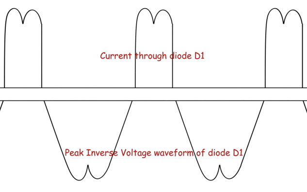
The voltage and current across the diode D1 are as shown below.
We can see from the voltage waveform above that the PIV, Peak Inverse Voltage, which is the maximum voltage faced by the diode when reverse biased, is √3 Vm-phase.
Add THD for line current