- Capacitor Bank Definition: A capacitor bank is defined as a group of capacitors used to store and release electrical energy in a power system, helping to improve power quality.
- System Voltage Tolerance: Capacitor banks must operate smoothly at up to 110% of the rated peak phase voltage and 120% of the rated RMS phase voltage.
- KVAR Rating: Capacitor units are rated by their KVAR values, which determine the reactive power they can provide to the system.
- Heat Management: Proper ventilation and spacing are necessary to manage heat from external and internal sources to maintain capacitor bank efficiency.
- Capacitor Unit Configurations: Capacitor units can be configured as single-phase or three-phase with different bushing arrangements to suit various power system requirements.
A shunt capacitor bank supplies reactive power and must tolerate specified electrical, thermal and mechanical stresses. Ratings and capability limits depend on the applicable standard, edition, voltage class and manufacturer. The bank should be designed to operate at or below its nameplate ratings during normal service.
- 110% of rated rms voltage.
- 120% of rated peak voltage, including harmonics but excluding transients.
- 135% of nominal rms current based on rated voltage and rated kVAR.
- 135% of rated kVAR.
Voltage Rating of Capacitor Bank
A shunt capacitor unit is often single-phase and is rated by the rms voltage across its terminals. Under the IEEE contingency capability criteria, rms voltage must not exceed 110% of rating and the peak, including harmonics but excluding transients, must not exceed 120% of rated peak. Rated peak for a sinusoid is  times rated rms voltage. These limits are not nominal design targets, and the current and kVAR limits must also be satisfied.
KVAR Rating of Capacitor Unit
A capacitor unit’s kVAR rating states its reactive-power output at rated voltage and frequency. Common catalogue sizes include, but are not limited to, the following values.
50 kVAR, 100 kVAR, 150 kVAR, 200 kVAR, 300 kVAR and 400 kVAR.
For a sinusoidal single-phase unit, the reactive power supplied to the power system varies with frequency, capacitance and the square of terminal voltage. A three-phase bank calculation must also account for its star, delta or series-parallel connection.
Temperature Rating of a Capacitor Bank
Two main heat sources affect a capacitor bank.
- External heating comes from ambient air, direct solar radiation and nearby equipment such as furnaces. Enclosures and restricted airflow can raise the local temperature above the recorded site ambient.
- Internal dielectric and conductor losses generate heat while the capacitor supplies reactive power. Harmonic current and overvoltage can increase this heating.
The installation must dissipate this heat without exceeding the unit’s temperature category. Use the governing standard and manufacturer instructions for ambient limits, solar exposure, mounting orientation, spacing and any enclosure-temperature allowance.
Maximum Ambient Temperature

Treat the table as a standard-specific temperature category, not a universal limit. Maintain the specified clearances between units so natural convection can remove heat. Forced ventilation may be required in an enclosure, at high ambient temperature or where solar and nearby equipment add heat.
Capacitor Bank Unit or Capacitor Unit
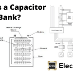
A Capacitor bank contains interconnected capacitor units plus switching, protection, discharge and support equipment. Individual units may be single-phase or three-phase, but medium-voltage and high-voltage banks commonly combine many single-phase units.
Single Phase Capacitor Unit
A single-phase capacitor unit can have one or two bushings. The choice determines whether both terminals are insulated from the tank or the metal tank forms one electrical terminal.
Double Bushing Capacitor Unit
In a two-bushing unit, both ends of the internal capacitor-element assembly connect through insulated bushings. The series-parallel element assembly is sealed inside the metal tank with its dielectric system. Neither terminal conductor is intentionally connected to the case, so the tank can be grounded independently. This arrangement is commonly called a dead-tank capacitor unit.
Single Bushing Capacitor Unit
In a one-bushing unit, one end of the capacitor-element assembly connects to the insulated bushing and the other connects internally to the metal case. The tank is therefore an electrical terminal and may be live or grounded according to the bank design. Installation clearances and handling must match that construction.
Three Bushing Capacitor Unit
A three-phase, three-terminal capacitor unit brings one terminal for each phase through a bushing. The internal star or delta connection determines the voltage across each element group. The arrangement described here has no separate neutral terminal; other three-phase constructions can use different terminal layouts.
BIL or Basic Impulse Insulation Level of Capacitor Unit
Like other high-voltage equipment, a capacitor bank must withstand specified power-frequency voltage stresses and impulse stresses from lightning and switching.
The required Basic Insulation Level, more precisely basic impulse insulation level, must coordinate with the system voltage, grounding, surge arresters, clearances and applicable standard. The unit nameplate states its insulation rating.
Internal Discharge Device
Capacitor units commonly include an internal discharge resistor that reduces residual terminal voltage after disconnection. Under typical IEEE requirements, units above 600 V reach 50 V or less within five minutes; lower-voltage and special units can have different times. The device does not make the bank immediately safe. Workers must follow the specified wait, test, shorting and grounding procedure.
Transient Over Current Rating
Switching a power capacitor can produce high transient current, especially during back-to-back energisation. Faults can also discharge stored bank energy through a failed unit. The capacitor, switching device, fuses, reactors, conductors and protection must withstand the specified current magnitude, frequency and duration.
A capacitor unit nameplate and data sheet should state the ratings needed to apply it safely.
The exact set depends on the governing standard and product.
A typical specification includes the following items.
- Nominal system voltage in kV.
- Rated power-system frequency in Hz.
- Temperature category and permitted minimum and maximum temperature in oC.
- Rated terminal voltage per unit in kV.
- Rated reactive-power output in kVAR.
- Rated capacitance in µF and its tolerance.
- Rated rms current in A.
- Rated power-frequency and impulse insulation levels.
- Residual discharge voltage and the time to reach it.
- Fusing arrangement: internally fused, externally fused or fuseless.
- Number of bushings and whether the tank is live or isolated.
- Number of phases and internal connection where applicable.