

- Schering Bridge Definition: The Schering Bridge is defined as an electrical circuit used for precise measurements of a capacitor’s capacitance, dissipation factor, and the relative permittivity of materials.
- Measuring Capacitance: The Schering Bridge measures capacitance by adjusting the impedance of its components to balance the bridge, where no voltage is detected across specific points.
- Components and Configuration: Essential components of a Schering Bridge include standard and variable capacitors, as well as non-inductive resistors, all crucial for accurate measurements.
- High Voltage Application: High voltage Schering Bridges are specifically used for measuring small capacitances in materials that require high voltages for better precision.
- Calculating Relative Permittivity: Relative permittivity is calculated from the capacitance measured across a specimen, considering factors like electrode area and spacing, enhancing understanding of material properties.
Schering Bridge Theory
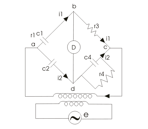
The Schering Bridge is designed to measure a capacitor’s capacitance, dissipation factor, and relative permittivity. Below is an illustration of the Schering Bridge circuit:
Here, c1 is the unknown capacitance whose value is to be determined with series electrical resistance r1.
c2 is a standard capacitor.
c4 is a variable capacitor.
r3 is a pure resistor (i.e. non inductive in nature).
And r4 is a variable non inductive resistor connected in parallel with variable capacitor c4. Now the supply is given to the bridge between the points a and c. The detector is connected between b and d. From the theory of ac bridges we have at balance condition,

Substituting the values of z1, z2, z3 and z4 in the above equation, we get


By separating and equating the real and imaginary parts of the equation, we obtain:

Let us consider the phasor diagram of the above Shering bridge circuit and mark the voltage drops across ab,bc,cd and ad as e1, e3,e4 and e2 respectively. From the above Schering bridge phasor diagram, we can calculate the value of tanδ which is also called the dissipation factor.
The equation that we have derived above is quite simple and the dissipation factor can be calculated easily. Now we are going to discuss high voltage Schering Bridge in detail. As we have discussed that simple schering bridge (which uses low voltages) is used for measuring dissipation factor, capacitance and measurement of other properties of insulating materials like insulating oil etc.
Why use a high voltage Schering Bridge? Simply put, measuring small capacitances accurately requires applying higher voltages and frequencies than low-voltage setups, which can be less effective. Let us discuss more features of this high voltage Schering Bridge:
- The bridge arms ab and ad consists of only capacitors as shown the bridge given below and impedances of these two arms are quite large as compared to the impedances of bc and cd. The arms bc and cd contains resistor r3 and parallel combination of capacitor c4 and resistor r4 respectively. As impedances of bc and cd are quite small therefore drop across bc and cd is small. The point c is earthed, so that the voltage across bc and dc are few volts above the point c.
- The high voltage supply is obtained from a transformer 50 Hz and the detector in this bridge is a vibration galvanometer.
- The impedances of arms ab and ad very are large therefore this circuit draws low current hence power loss is low but due to this low current we need a very sensitive detector to detect this low current.
- The fixed standard capacitor c2 has compressed gas which works as dielectric therefore dissipation factor can be taken as zero for compressed air. Earthed screens are placed between high and low arms of the bridge to prevent errors caused due to inter capacitance.
Let us study how Schering bridge measures relative permittivity:
To measure relative permittivity, we first determine the capacitance of a small capacitor using the specimen as a dielectric. From this measurement, calculating the relative permittivity becomes straightforward with the following relation:
Where, r is relative permeability.
c is the capacitance with specimen as dielectric.
d is the spacing between the electrodes.
A is the net area of electrodes.
and ε is permittivity of free space.
There is another way to calculate relative permittivity of the specimen by changing electrode spacing. Let us consider diagram shown below
Here A is the area of electrode.
d is the thickness of the specimen.
t is the gap between the electrode and specimen (here this gap is filled by compressed gas or air).
cs is the capacitance of specimen.
co is capacitance due to spacing between electrode and specimen.
c is the effective combination of cs and co.
From figure above, as two capacitors are connected in series,
εo is permittivity of free space, εr is relative permittivity, when we remove specimen and the spacing readjusted to have same value of capacitance, the expression for capacitance reduces to
On equating (1) and (2), we will get the final expression for of εr as: