

- Synchronous Motor Definition: A synchronous motor is defined as an AC motor where the shaft rotation matches the frequency of the supply current.
- Synchronous Motor Circuit Diagram: The synchronous motor circuit diagram includes terminal voltage, effective resistance, leakage reactance, fictitious reactance, and synchronous reactance.
- Counter EMF: Counter EMF is the voltage induced in the stator winding due to the rotating magnetic field, which opposes the applied voltage.
- Zero Power Factor Method: This method involves plotting the armature terminal voltage against the field current at zero lagging power factor to measure synchronous reactance.
- Potier Triangle: A graphical representation used to determine synchronous reactance by forming a triangle that represents different voltage drops.
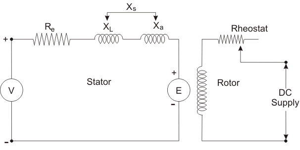
V = Terminal voltage
Re = Effective resistance
XL = Leakage reactance
Xa = Fictious reactance
Xs = Synchronous reactance
E = Counter emf
In a synchronous motor, the revolving field structure is energized by direct current (DC). In the stator winding, two effects are considered: the effect of the field cutting stator conductors at synchronous speed and the effect of the stator’s revolving field. This induces a voltage in the stator winding.
This voltage, called counter EMF (E), opposes the applied voltage (V) to the stator. The magnitude of the induced EMF depends on the strength of the excitation current. In the stator, two types of reactance are considered: leakage reactance and fictitious reactance.
The effect of armature reaction can be substituted by fictitious reactance (Xa) which when combined with the leakage reactance of the armature gives synchronous reactance (Xs) combined with the armature effective resistance (Re) gives the synchronous impedence (Zs).
Zero Power Factor Method or Potier Triangle
Before discussing the Potier triangle we have to discuss Potier characteristic. The Zero-power factor characteristic (ZPFC) of an alternator is a curve of the armature terminal voltage per phase plotted against the field current with constant rated armature current at synchronous speed and zero lagging power factor (p.f.).
To maintain a very low power factor (zero), the alternator is loaded by an under-excited synchronous motor. The shape of the zero power factor characteristic graph is similar to the Open Circuit Characteristic (O.C.C.) but displaced downward horizontally.
The Phasor diagram as follows –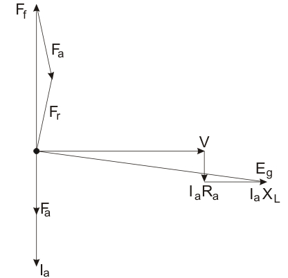
Here,
Y = Terminal voltage
Ia = Armature current
Ra = Armature resistance
XL = Leakage reactance
Eg = Generated voltage per phase
Fa = Armature reaction mmf
Ff = Field mmf
Fr = Resultant emf
If we neglect the armature resistance the Phasor will as follows-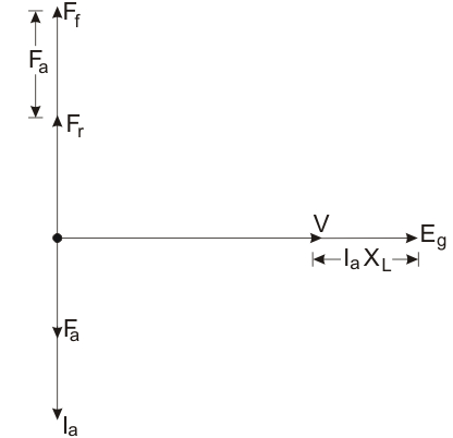
Taking the reference terminal voltage at zero p.f. lagging, the armature current lag behind voltage by 90o. Here IaRa parallel to Ia, IaXL perpendicular to Ia.
Then we can say that from first phasor diagram
From the second phasor diagram we can say that terminal voltage (V), the reactance voltage drop (IaXL), and the generated voltage (Eg) are in phase.
The arithmetically we say that :
Also the three mmf phasor are in phase so that we can say that :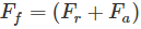
If we convert this equation into the equivalent field current by dividing its both sides by Tf which is the effective number of turns per pole on the roter field.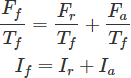
Where,
If = Field current
Ir = Resultant current
Ia = Armature current
Let consider ‘b’ at zero p.f. carve at rated terminal voltage (v) and field current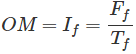
The armature current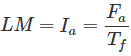
Resultant current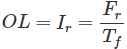
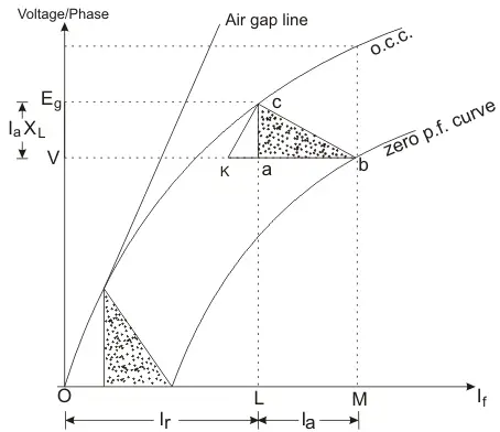
The field current OL would result in generated
So that the vertical distance AC must be equal to leakage – reactance voltage drop (IaXL)
The triangle formed by the vertices a, b, c called Potier Triangle.
