- Buck Converter Definition: A buck converter is a type of DC-DC converter that steps down a higher input voltage to a lower output voltage.
- Circuit Components: The main components include a switch (usually a MOSFET or IGBT), a diode, and an LC filter, each vital for the converter’s functionality.
- Pulse Width Modulation (PWM): PWM controls the timing of the switch in a buck converter, crucial for regulating output voltage and minimizing ripples.
- Modes of Operation: In Mode I, the switch is on and the diode is off, vice versa for Mode II, each mode essential for continuous current flow through the load.
- Steady State Analysis: Analysis of the buck converter in steady state demonstrates that the inductor current remains constant overall, ensuring a stable output.
DC-DC converters, often called Choppers, include the Buck converter, which steps down a higher input DC voltage to a lower specified output voltage.
A typical Buck converter is shown below.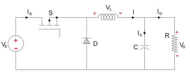
The input vvoltage source connects to a controllable solid-state device like a Power MOSFET or IGBT, which acts as a switch. Unlike Thyristor, which require complex additional circuitry to turn off, MOSFETs and IGBTs simply need zero voltage across specific terminals to deactivate.
Alongside the main switch, a diode serves as the secondary switch. Both are linked to an LC filter, meticulously designed to minimize ripples in current and voltage, with the circuit completed by a purely resistive load.
The input voltage remains constant, as does the current through the load, effectively treating the load as a stable current source.
Pulse Width Modulation (PWM), which may be either time-based or frequency-based, controls the switch. Time-based PWM is preferred as frequency-based PWM complicates the design due to its wide frequency range, which makes the LC filter design more complex.
Time based Modulation is mostly used for DC-DC converters. It is simple to construct and use. The frequency remains constant in this type of PWM modulation.
The Buck converter has two modes of operation. The first mode is when the switch is on and conducting.
Mode I : Switch is ON, Diode is OFF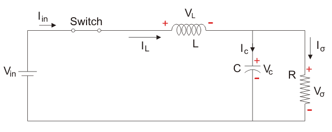
The voltage across the capacitance in steady state is equal to the output voltage.
Let us say the switch is on for a time TON and is off for a time TOFF. We define the time period, T, as  and the switching frequency,
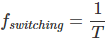
Let us now define another term, the duty cycle, 
Let us analyse the Buck converter in steady state operation for this modeusing KVL.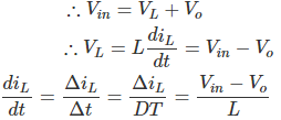
Since the switch is closed for a time TON = DT we can say that Δt = DT.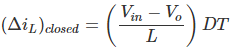
While performing the analysis of the Buck converter, we have to keep in mind that
- The inductor current is continuous and, this is made possible by selecting an appropriate value of L.
- The inductor current in steady state rises from a value with a positive slope to a maximum value during the ON state and then drops back down to the initial value witha negative slope. Therefore the net change of the inductor current over anyone complete cycle is zero.
Mode II: Switch is OFF, Diode is ON
Here, the energy stored in the inductor is released and is ultimately dissipated in the load resistance, and this helps to maintain the flow of current through the load. But for analysis we keep the original conventions to analyse the circuit using KVL.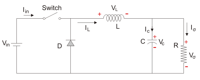
Let us now analyse the Buck converter in steady state operation for Mode II using KVL.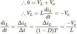
Since the switch is open for a time  we can say that Δt = (1- D)T.
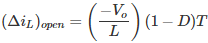
It is already established that the net change of the inductor current over anyone complete cycle is zero.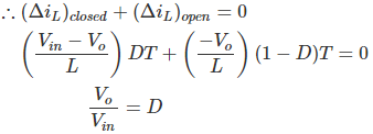
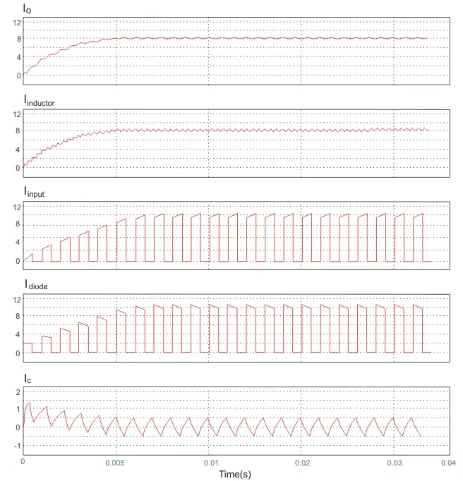
A circuit of a Buck converter and its waveforms is shown below.
The inductance, L, is 20mH and the C is 100µF, and the resistive load is 5Ω. The switching frequency is 1 kHz. The input voltage is 100V DC, and the duty cycle is 0.5.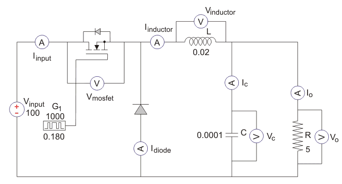
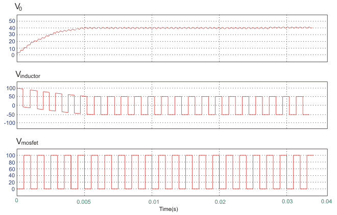
The voltage waveforms are as shown above and the current waveforms are as shown in the figure below.