

- Bridge Rectifier Definition: A bridge rectifier is a circuit that converts AC to DC using four diodes arranged in a bridge configuration.
- Working Principle: It works by allowing current to flow through different pairs of diodes based on the input polarity, ensuring the output polarity remains the same.
- Circuit Diagram: The diagram includes four diodes connected to an AC input and a load resistor, showing how current flows in each cycle.
- Pulsating DC Output: The output is pulsating DC, which can be smoothed using a capacitor to reduce ripples.
- Applications: Bridge rectifiers are used in high voltage applications, radio signal detection, and welding.
What is a Bridge Rectifier?
Bridge rectifiers are similar to half-wave rectifiers and full-wave rectifiers. They use four diodes (D1, D2, D3, and D4). The input is supplied across terminals A and B, and the output is collected across a load resistor (RL) connected between terminals C and D.

When a positive pulse appears at the AC input (terminal A is positive, terminal B is negative), diodes D1 and D3 become forward biased, while diodes D2 and D4 are reverse biased.
As a result, the current flows along the short-circuited path created by the diodes D1 and D3 (considering the diodes to be ideal), as shown by Figure 2a. Thus the voltage developed across the load resistor RL will be positive towards the end connected to terminal D and negative at the end connected to the terminal C.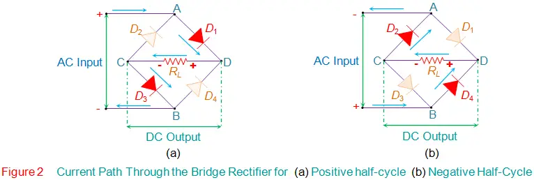
When a negative pulse appears at the AC input (terminal A is negative, terminal B is positive), diodes D2 and D4 become forward biased, while diodes D1 and D3 are reverse biased.
It’s important to note that the voltage across RL remains the same polarity regardless of whether the AC input pulse is positive or negative. Thus, the output of the bridge rectifier always has the same polarity, as shown by the waveforms in Figure 3.
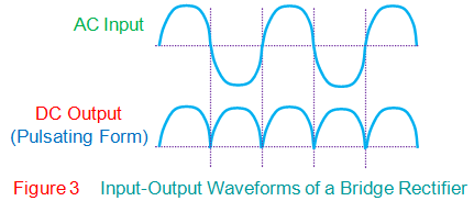
However, it is to be noted that the bridge rectifier’s DC will be pulsating in nature. In order to obtain a pure form of DC, one has to use a capacitor in conjunction with the bridge circuit (Figure 4).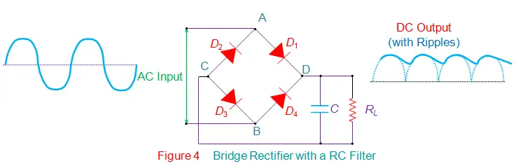
In this design, the positive pulse at the input causes the capacitor to charge through the diodes D1 and D3. However as the negative pulse arrives at the input, the charging action of the capacitor ceases and it starts to discharge via RL.
This results in the generation of DC output which will have ripples in it as shown in the figure. This ripple factor is defined as the ratio of the AC component to the DC component in the output voltage. In addition, the mathematical expression for the ripple voltage is given by the equation
Where,
Vr represents the ripple voltage.
Il represents the load current.
f represents the frequency of the ripple which will be twice the input frequency.
C is the Capacitance.
Further, the bridge rectifiers are primarily of two types, viz., Single-Phase Rectifiers and Three-Phase Rectifiers. In addition, each of these can be either Uncontrolled or Half-Controlled, or Full-Controlled.
Bridge rectifiers for a particular application are selected by considering the load current requirements. These bridge rectifiers are quite advantageous as they can be constructed with or without a transformer and are suitable for high voltage applications.
However, here two diodes will be conducting for every half-cycle and thus the voltage drop across the diodes will be higher. Lastly one has to note that apart from converting AC to DC, bridge rectifiers are also used to detect the amplitude of modulated radio signals and to supply polarized voltage for welding applications.