

- Keyboard Encoder Definition: A keyboard encoder is a device that converts signals from a keyboard matrix into serial data for external devices.
- Types of Encoders: There are hardware-based and software-based keyboard encoders.
- Hardware-Based Encoders: These use integrated circuits for fast and reliable encoding but are less flexible.
- Software-Based Encoders: These run on microcontrollers, offering flexibility and customization.
- Applications: Keyboard encoders are used in various devices, including computers, industrial keyboards, and custom keyboards.
What is a Keyboard Encoder?
A keyboard encoder is a device that converts the signals from a keyboard matrix into a serial format data word that can be transmitted to an external device, such as a computer or a microcontroller. A keyboard matrix is a grid of rows and columns of switches that represent the keys on a keyboard. Each switch has a unique combination of row and column coordinates that correspond to a specific key.
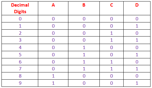
A keyboard encoder scans the keyboard matrix regularly to detect which key is pressed or released. It encodes this information into a binary-coded decimal (BCD) code or a scan code. BCD is a four-bit representation of a digit from 0 to 9, while a scan code uniquely identifies each key. The encoder sends this code to the external device via USB or PS/2.
Types of Keyboard Encoders
There are two main types of keyboard encoders: hardware-based and software-based.
Hardware-Based Keyboard Encoders
Hardware-based keyboard encoders are integrated circuits (ICs) that use logic gates, diodes, resistors, capacitors, and flip-flops to encode signals. They are designed for specific keyboard layouts with fixed matrix tables mapping row and column coordinates to BCD or scan codes. They are fast and reliable but inflexible and need extra components to interface with external devices.
An example of a hardware-based keyboard encoder is the SK5120, a low-power USB programmable encoder IC with an external PS/2 port and KeyMouse support. The SK5120 can be programmed for any keyboard layout, making it ideal for custom keyboards. It also supports one external PS/2 device, like a touchpad, and can emulate PS/2 mouse actions with its 8-direction KeyMouse feature.
Another example is the KE24, a programmable PS/2 interface that scans a matrix up to 12 x 12 or 24 individual inputs. It also has an RS-232 serial port for communicating with other devices. The KE24 can be programmed with custom keystrokes or macro sequences using Windows® software.
Software-Based Keyboard Encoders
Software-based keyboard encoders are programs running on microcontrollers or microprocessors with access to the keyboard matrix. They use software algorithms to scan the matrix, detect key events, and generate BCD or scan codes. These encoders are more flexible and customizable than hardware ones but need more programming skills and memory resources.
An example of a software-based keyboard encoder is the Arduino Keyboard Library, which allows an Arduino board to act as a USB HID (Human Interface Device) keyboard. The library uses the Arduino pins to connect to the keyboard matrix and provides functions to read the key states and send keystrokes to the computer. The library also supports modifier keys, such as SHIFT, CTRL, ALT, etc.
Applications of Keyboard Encoders
Keyboard encoders are widely used in various applications that require human-machine interaction through keyboards, such as:
- Computers
- Laptops
- Netbooks
- Industrial keyboards
- Point-of-sale (POS) terminals
- Portable devices
- Custom keyboards
Keyboard encoders enable keyboards to communicate with different devices using standard protocols, such as USB or PS/2. They also allow keyboards to have additional features, such as macro keys, custom keys, mouse emulation, etc.
Conclusion
A keyboard encoder is a device that converts the signals from a keyboard matrix into a serial format data word that can be transmitted to an external device. There are two main types of keyboard encoders: hardware-based and software-based. Hardware-based keyboard encoders are integrated circuits that perform the encoding function using logic components, while software-based keyboard encoders are programs that run on microcontrollers or microprocessors that have access to the keyboard matrix. Keyboard encoders are widely used in various applications that require human-machine interaction through keyboards.