

- Monostable Multivibrator Definition: A monostable multivibrator is defined as a relaxation oscillator that produces a single output pulse of a specified duration when triggered by an external signal.
- Working Principle: It has one stable state and one unstable state, automatically returning to the stable state after a set time period.
- RC Time Constant: The output pulse duration depends on the RC time constant, adjustable by changing the resistor and capacitor values.
- Applications: These circuits are widely used in timing applications like timers, delay circuits, frequency dividers, pulse generators, and pulse shapers.
- Advantages and Disadvantage: Monostable multivibrators are simple and cost-effective but have limitations such as needing external triggers and being sensitive to temperature changes.
A monostable multivibrator is defined as a relaxation oscillator that produces a single output pulse of a specified duration when triggered by an external signal. It has one stable state and one unstable state, returning to the stable state automatically after a set period. The pulse duration is determined by the RC time constant of the circuit, adjustable by changing the resistor and capacitor values.
Monostable multivibrators are also known as one-shot, single-shot, single-swing, delay, or un-vibrator circuits. They are widely used in timing applications, such as timers, delay circuits, frequency dividers, pulse generators, and pulse shapers.
How Does a Monostable Multivibrator Work?
A monostable multivibrator can be constructed using various components, such as transistors, op-amps, or 555 timer ICs. Here, we will explain the working principle of a monostable multivibrator using two bipolar junction transistors (BJTs).
The circuit includes two BJTs (Q1 and Q2), a capacitor (C), and four resistors (RC1, RC2, R1, and R2). The output is taken from the collector of Q2.
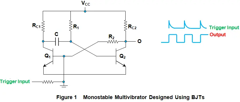
Initially, the circuit is in its stable state, where Q1 is off, and Q2 is on. The output is low, as the collector of Q2 is shorted to ground. The right plate of the capacitor C is at 0.7 V, as it is connected to the base of Q2, while the left plate of the capacitor C is charging gradually towards VCC through R1.
When a positive trigger pulse T is applied to the base of Q1, it turns on and conducts current through RC1. This causes the collector of Q1 and the left plate of the capacitor C to drop to the ground. The capacitor C discharges through R1 and Q1, creating a negative voltage across its plates. This negative voltage turns off Q2, as its base-emitter junction is reverse-biased.
This state of the circuit is unstable, as Q1 is on and Q2 is off. The output is high, as the collector of Q2 is at VCC. The capacitor C continues to discharge until its voltage reaches zero.
When the base-emitter junction of Q2 becomes forward-biased again, Q2 turns on. The collector of Q2 and the right plate of the capacitor C drop to ground. The capacitor C starts charging again through R2 and Q2, creating a positive voltage that turns off Q1 as its base-emitter junction is reverse-biased.
The circuit returns to its stable state, where Q1 is off, and Q2 is on. The output is low, as the collector of Q2 is shorted to ground. The capacitor C continues to charge until its voltage reaches 0.7 V.
Monostable multivibrators have several advantages and disadvantages compared to other types of multivibrators or oscillators. These include:

Where T is the pulse width, R1 is the resistance in ohms, and C is the capacitance in farads.
The frequency of the output pulse depends on how often the trigger pulse T is applied to the base of Q1. However, it should be noted that the trigger pulse should be shorter than the pulse width T, and there should be enough time between two consecutive trigger pulses for the capacitor C to fully charge again. Otherwise, the output pulse may not reach its full amplitude or duration.
Applications of Monostable Multivibrators
Monostable multivibrators are useful for generating fixed-duration pulses that are sensitive to some external event or signal. Some examples of their applications are:
- Timers: Monostable multivibrators can be used to create timers that produce a delay or a timeout after a trigger signal. For example, they can be used to turn off a device after a certain time period or to activate an alarm after a preset interval.
- Delay circuits: Monostable multivibrators can be used to create delay circuits that introduce a lag or a phase shift between an input signal and an output signal. For example, they can be used to synchronize signals in digital systems or to delay signals in analog systems.
- Gated circuits: Monostable multivibrators can be used to create gated circuits that enable or disable an output signal based on a trigger signal. For example, they can be used to gate an oscillator or a counter or to switch between two signals.
- Frequency dividers: Monostable multivibrators can be used to create frequency dividers that reduce the frequency of an input signal by a factor of two or more. For example, they can be used to divide a clock signal or a carrier signal by using multiple stages of monostable multivibrators.
- Pulse generators: Monostable multivibrators can be used to create pulse generators that produce single or multiple pulses with precise widths and intervals. For example, they can be used to generate pulses for sampling signals or for testing circuits.
- Pulse shapers: Monostable multivibrators can be used to create pulse shapers that modify or improve the shape or quality of an input signal. For example, they can be used to sharpen or smooth pulses or to eliminate noise or glitches.
Advantages and Disadvantages of Monostable Multivibrators
Monostable multivibrators have some advantages and disadvantages compared to other types of multivibrators or oscillators. Some of them are:
- Advantages:
- They are simple in design and inexpensive.
- They produce perfect square waves at their output with no distortion.
- They have high noise immunity and stability.
- They can operate over a wide range of frequencies and voltages.
- They can be easily triggered by various types of signals.
- Disadvantages:
- They require external triggering for their operation.
- They have limited duty cycle range and accuracy.
- They have low power efficiency and high power dissipation.
- They may have false triggering due to stray capacitance or leakage currents.
- They may have variations in their output pulse width due to temperature changes or component tolerances.
Summary
A monostable multivibrator is a type of relaxation oscillator that produces a single output pulse when triggered by an external signal.
It has one stable state and one unstable state, and it returns to the stable state automatically after a certain time period.
The duration of the output pulse is determined by the RC time constant of the circuit, which can be adjusted by changing the values of the resistor and capacitor.
Monostable multivibrators are widely used in timing applications, such as timers, delay circuits, frequency dividers, pulse generators, and pulse shapers.
They are simple in design and inexpensive but have some limitations in terms of duty cycle range, accuracy, power efficiency, and false triggering.