
- High Pass Filter Definition: A high pass filter allows frequencies higher than a certain cutoff and blocks lower ones, useful in electronic filtering.
- Circuit Components: These filters can use simple components like resistors and capacitors or include operational amplifiers for more complex applications.
- High Pass Filter Transfer Function: The transfer function mathematically represents how the filter processes signals, emphasizing frequencies above the cutoff.
- Bode Plot Overview: A Bode plot visualizes the frequency response of the filter, showing changes in signal magnitude and phase with frequency.
- Practical Applications: High pass filters are used in diverse fields like audio technology and image processing to enhance signal quality.
A filter removes unwanted elements, much like a water filter cleans impurities from water. Similarly, an electric filter works to cleanse signals in electronic circuits.
An electric filter, made up of resistors, inductors, capacitors, and amplifiers, passes signals of a certain frequency while attenuating others that are too high or too low.
The frequency at which filter operates, that frequency is known as cut-off frequency. The cut-off frequency is set while designing the filter.
What is a High Pass Filter?
A high pass filter (also known as a low-cut filter or bass-cut filter) is an electronic filter that permits signals with a frequency higher than a certain cutoff frequency and attenuates signals with frequencies lower than that cutoff frequency.
The inverse of a high-pass filter is a low-pass filter, which allows signals with frequencies lower than the cut-off frequency and blocks all frequencies above this cut-off frequency. There are also band pass filters, which combine the functionality of high pass filters and low pass filters to only allow frequencies within a specific frequency range.
High Pass vs Low Pass Filters
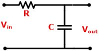
The characteristics of a high pass filter are exactly the opposite characteristics of a low pass filter. The difference include:High Pass Filter (HPF) Low Pass Filter (LPF) Definition HPF is an electric filter that allows signals with higher frequency than the cut-off frequency. It is known as the low-cut filter. LPF is an electric filter that allows signals with a lower frequency than the cut-off frequency. It is known as the high-cut filter. Circuit Diagram In HPF, the capacitor followed by the resister. In LPF, the resister followed by the capacitor. RC Filter 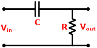
Operating frequency Higher than the cut-off frequency Lower than the cut-off frequency. Importance It is important to cancel the low-frequency noise from the input signal. It is important to cancel the aliasing effect. Applications It is used in amplifiers like an audio amplifier, low-noise amplifier. It used in communication circuits as an anti-aliasing filter.
Types of High Pass Filters
There are many types of high-pass filters according to the circuit design and components used to make a filter. The various types of high-pass filters include:
Passive High Pass Filter
The passive filter consists of only passive elements like resistor, inductor, and capacitor. It will not use any external power source or amplification components.
A passive high pass filter consists of a combination of resistor and capacitor (RC) or resistor and inductor (RL).
Active High Pass Filter
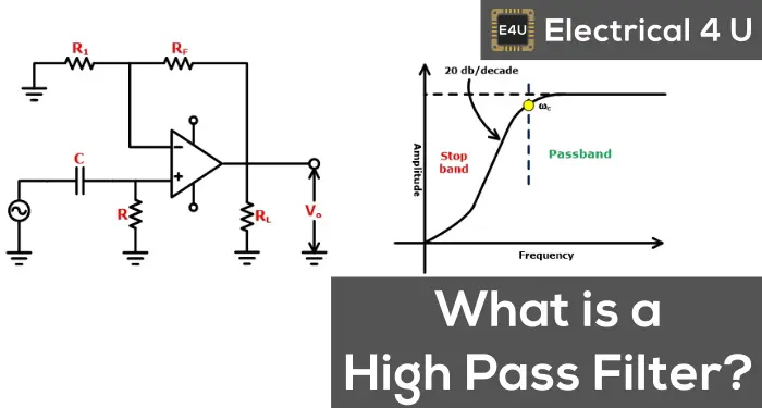
The Active filter is a combination of a passive filter with an operational amplifier (OP-AMP) or it includes an amplifier with gain control.
It is made by connecting an inverting or non-inverting component of OP-AMP with a passive filter.
RC High Pass Filter
The RC filter is one type of passive filter because it consists only of a capacitor is in series with the resistor.
The circuit diagram of high pass and low pass filter is the same, just interchange the capacitor and resistor. The circuit diagram of the RC high pass filter is as shown in the below figure.
The capacitor offers very high reactance for the signal with a frequency lower than the cut-off frequency. In this case, the capacitor act as an open switch.
The capacitor offers low reactance for the signal with a frequency higher than the cut-off frequency. In this case, the capacitor act as a close switch.
First Order High Pass Filter
First Order High pass filter consists of only one capacitor or inductor. This type of filter has a transfer function of the first order.
It means if you derive an equation in s-domain, the maximum power of ‘s’ is one. This is only possible if you use only one energy storage element like inductor and capacitor.
The first order filter can be active or passive, depending on the use of elements. If it uses only active elements, it can be a first-order filter. RC high pass filter is a first-order passive high pass filter.
Second Order High Pass Filter
Second-Order high pass filter can derive by cascading two first-order high pass filters. Therefore, it consists of two reactive components and makes a second-order circuit.

The main difference in the first order and second-order filter slope in the stop band. The slop of the second-order filter is twice of the first-order filter.

For example, if we consider a first-order Butterworth filter, the slop is +20 db/decade and for second-order Butterworth filter, the slop is +40 db/decade.
Butterworth High Pass Filter
The Butterworth filter is designed to have a flat frequency response in the pass band. So, in the pass band, there is no ripple in the frequency response. The below figure shows the circuit diagram of the first order and second-order Butterworth high pass filter with frequency response.

Chebyshev High Pass Filter
In all ranges of filters, the Chebyshev filter minimizes the error between the actual filter and the ideal filter. There are two types of filters; type-I and type-II. The type-I filter is known as “Chebyshev Filter” and the type-II filter is known as “Inverse Chebyshev Filter”.

This filter response is optimal trade between ripple and slope. If the ripple is set to 0%, the filter response is the same as the Butterworth Filter. But a ripple of 0.5% is a good choice for digital filters which make sharp slop. Below figure shows difference in frequency response for Butterworth and Chebyshev filter.

If the ripple present at the pass band, the filter is known as type-I Chebyshev Filter and if the ripple present in the stop band, the filter is known as type-II Inverse Chebyshev Filter.

There is a very fast transition between the pass band and stop band. But for this condition, the ripple will present in pass band and stop band. This type of filter is known as Elliptical Filter.
Bessel Filter
The Butterworth filter has good transient and amplitude behavior. Chebyshev filter has a good amplitude response than Butterworth filter with the expense of transient behavior.
The Bessel filter has a good transient response. But the amplitude behavior is poor. The Bessel filter is designed to get a constant group delay in the pass band.
Passive vs Active High Pass Filter
According to the components used in the circuit, filters are classified into two types; Active Filter and Passive Filter.Active Filter Passive Filter Circuit elements Active Filter uses active elements like OP-AMP and Transistor. Passive Filter uses passive elements like Capacitor and Inductor. Extra power supply It requires an extra power supply. It operates on the signal input and not need an extra power supply. Frequency limitation It has frequency limitations. It has no frequency limitations. Cost High Cheaper in cost. Stability Inferior stability Better stability Weight Low High (Because the weight of inductor is very high) Sensitivity More sensitive Less sensitive Q Factor High Very Low Design It needs a complex control system. So, the design of this filter is complex. It is easy to design. Efficiency High Low Frequency Response Characteristic Frequency Response Characteristic is sharp Frequency Response Characteristic is not sharp
High Pass Filter Transfer Function Equation
The transfer function gives mathematical representation of filters. This mathematical expression gives the input to output behavior of the filter.
The transfer function of a first order high pass filter is derived in the below equations.

Output Impedance is equal to:

Input Impedance is equal to:

The transfer function is defined as the ratio of Output voltage to input voltage.

The standard form of transfer function is as:

Where:


According to this transfer function for higher frequency

And for Lower frequency

Therefore, it shows zero magnitude for lower frequency and Maximum magnitude for higher frequency.


Cutoff Frequency High Pass Filter
The cutoff frequency is defined as a frequency that creates a boundary between pass band and stop band.
For a high pass filter, if the signal frequency is more than the cutoff frequency, then it will allow passing the signal. And if the signal frequency is less than the cutoff frequency, then it will attenuate the signal.
The cutoff frequency is defined by the user at the time of designing a filter. For the first-order RC high pass filter, it is expressed as below equation. This equation is the same for a high pass as well as a low pass filter.

The cutoff frequency for second-order high pass RC filter is determined by both the resistors and capacitors. And it expressed as;

From the above equation, if the value of R1 and R2 is equal and the value of C1 and C2 is equal than the equation is expressed as;

High Pass Filter Bode Plot or Frequency Response
The frequency response or bode plot of the high pass filter is totally opposite compared to the frequency response of the low pass filter.
Using the transfer function, we can plot a frequency response of the filter circuit. The magnitude curve and phase curve of the bode plot for high pass filter is as shown in the below figure.
The magnitude curve can be obtained by the magnitude of the transfer function.

The phase curve can be obtained by the phase equation of the transfer function.

Magnitude Plot
As shown in the magnitude curve, it will attenuate the low frequency at the slope of +20 db/decade. The region from an initial point to the cutoff frequency is known as stop band.
When it crosses the cutoff frequency, it will allow the signal to pass. And the region above the cutoff frequency point is known as a pass band.
At cutoff frequency point the output voltage amplitude is 70.7% of the input voltage.
Phase Plot
At cutoff frequency, the phase angle of the output signal is +45 degree. From the phase plot, the output response of the filter shows that it can pass to infinite frequency. But in practice, the output response does not extend to infinity.
By proper selection of components, the frequency range of filter is limited.
Ideal High Pass Filter
The ideal high pass filter blocks all the signal which has frequencies lower than the cutoff frequency. It will take an immediate transition between pass band and stop band.
The magnitude response of the ideal high pass filter is as shown in the below figure. The amplitude will remain as original amplitude for signals which have a higher frequency than the cutoff frequency. And the amplitude will completely zero for signals which have a lower frequency than the cutoff frequency. Therefore, an ideal high pass filter has a flat magnitude characteristic.
The transfer function of ideal high pass filter is as shown in the equation below:

The frequency response characteristics of an ideal high pass filter is as shown in below figure.

This type of ideal characteristic of a high pass filter is not possible for practical filters. But the Butterworth filter characteristic is very close to the ideal filter.
Applications of High Pass Filters
The applications of high pass filters include:
- It is used in amplifiers, equalizers, and speakers to reduce the low-frequency noise.
- For sharpening the image, high pass filters are used in image processing.
- It is used in various control systems.